GE Industrial Solutions TEYD-H-L Circuit Breaker User Manual
Molded case circuit breaker
INSTALLATION INSTRUCTIONS
DEH41590
CR R1206972
Molded case circuit Breaker
INTRODUCTION
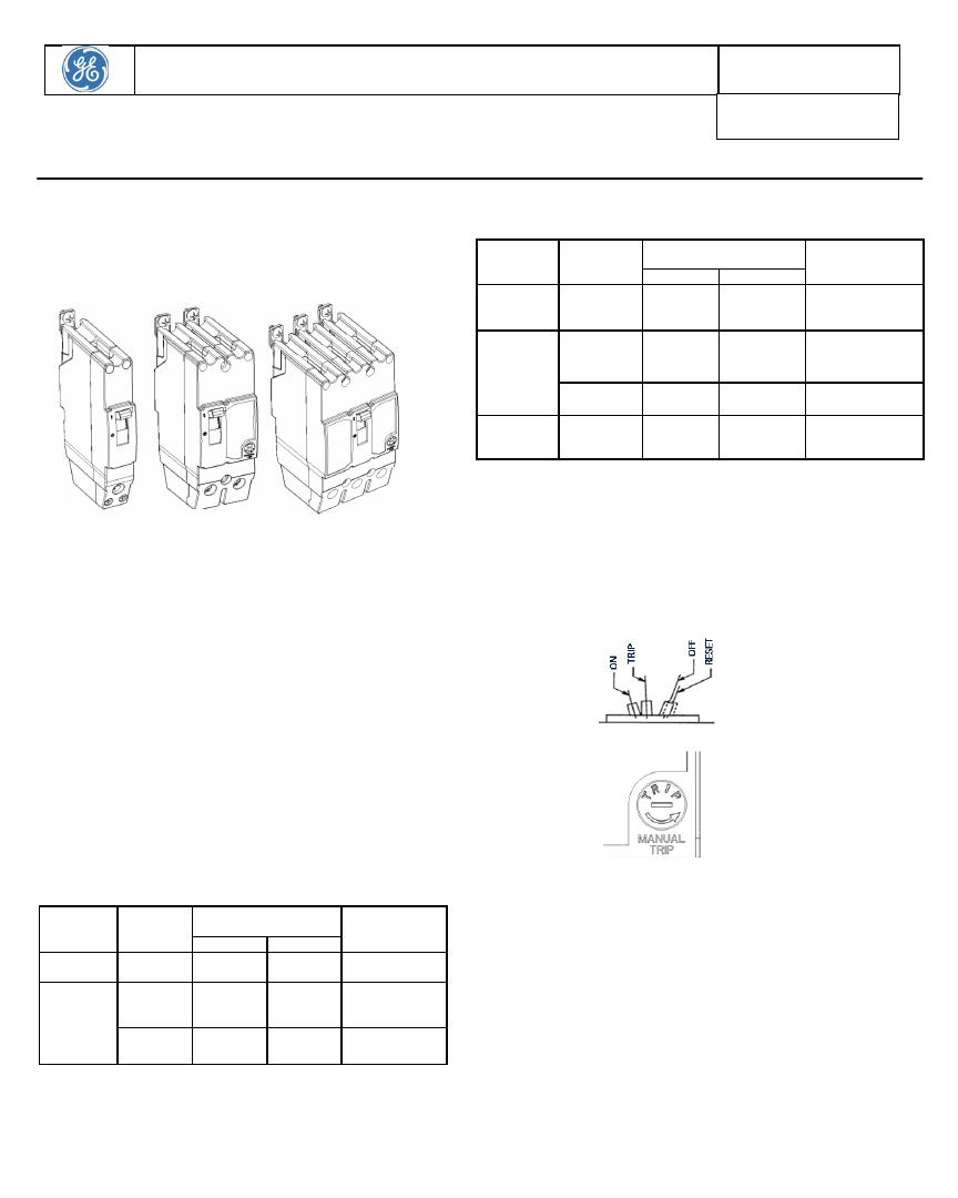
These instructions apply to UL 489 rated TEY D/H/L, TEY F (110 &
125 A only) series of thermal magnetic molded case circuit
breakers. These are available in 1, 2 & 3 pole configurations. The
1 pole is available from 15 to70A ratings while 2 pole & 3 pole are
available from 15A to 125A ratings. Fig 1 shows the 1, 2 & 3 pole
Fig 1.
DELIVERY CHECKS
Unpack the breaker from the box & inspect for any shipping damage.
Insure that the breaker has proper amperage, voltage & interrupting
ratings for the application. Also check the breaker operation as per
Fig 2. If breaker ordered is with accessory, check appropriate labels
are attached on the side on breaker with rating for accessory.
INSTALLATION
These circuit breakers are designed for dry, dust free & non
corrosive environment. If these conditions are not available then
it should be installed in enclosure or switchboards which provide
this protection.
The Breaker is provided with mounting clip at the bottom side &
screw connection at line end. Once the breaker is hooked into
the mounting clip then the line screws to be tightened to torque
of 25-32 LB-in.
WIRE CONNECTIONS
WIRE
CONNECTOR
USED ON
WIRE RANGE
LOAD EN D L UG
TORQUE TO WIRE
Cu
Al
A
(SA DDLE
CLAMP)
15A – 20A
#12 - #14
#10 - #12
#10, 12, 14, - 35
LB-in
B
(LUG)
30A – 60A
#10 - #6
#8 - # 4
#10 – 35 LB-in
#8 – 40 LB-in
#6, # 4 – 45 LB-in
70A
#4 - # 1
#2 - I/O
#4 –I/O – 45 LB-in
1 POLE
2 POLE & 3 POLE
WIRE
CONNECTOR
USED ON
WIRE RANGE
LOAD EN D L UG
TORQUE TO WIRE
Cu
Al
A
(SA DDLE
CLAMP)
15A – 20A
#12 - #14
#10 - #12
#10, 12, 14, – 35 LB-in
B
(LUG)
30A – 60A
#10 - #6
#8 - # 4
#10 – 35 LB-in
#8 – 40 LB-in
#6, # 4 – 45 LB-in
70A – 100A
#4 - # 1
#2 – I/O
#4 –I/O – 45 LB-in
C
(LUG)
110A – 125A
#3 – 3/O
#1 - 3/O
100 LB-in
OPERATION
The breaker contact status position is indicated by handle position &
positions are marked on the cover as ON (I) & OFF (O).
Breaker Operations are shown in Fig 2. To turn the breaker ON from OFF
position, move the handle to ON position. To turn the breaker ON from
TRIP position, move handle fully to RESET position & then switch ON.
To trip the breaker manually the breaker is provided with manual trip
feature for 2 pole & 3 pole configurations. Rotate the Twist the button in
direction as indicated on the twist button as shown in Fig 3.
Fig 2. Breaker operations
Fig 3. Manual trip Feature
MAINTENANCE
Refer to NEMA AB-4 for further maintenance and inspection information. It
is recommended the following operations be performed atleast annually.
1.
Turn off the power to the equipment being serviced.
2.
Clean the surfaces of the breaker & surrounding area of any
dirt, soot or other debris.
3.
Inspect the breaker for any damage
4.
Operate the mechanism by turning the breaker ON & OFF. Also
operate the trip function thru manual trip feature.