GE Industrial Solutions AF-650 GP 24V DC External Supply Module User Manual
Page 2
AF-650 GP & AF-600 FP
TM
24 V External Supply Instruction
imagination at work
The instructions do not purport to cover all details or variations in equipment nor to provide for every pos-
sible contingency to be met in connection with installation, operation or maintenance. Should further infor-
mation be desired or should particular problems arise which are not covered suff iciently for the purchas-
er's purposes, the matter should be referred to the GE company.
AF-650 GP and AF-600 FP are trademarks of the General Electric Company.
GE consumer & Industrial
41 Woodford Avenue
Plainville, CT 06062
www.geelectrical.com/drives
*MI33O122*
130R0144
DET-635
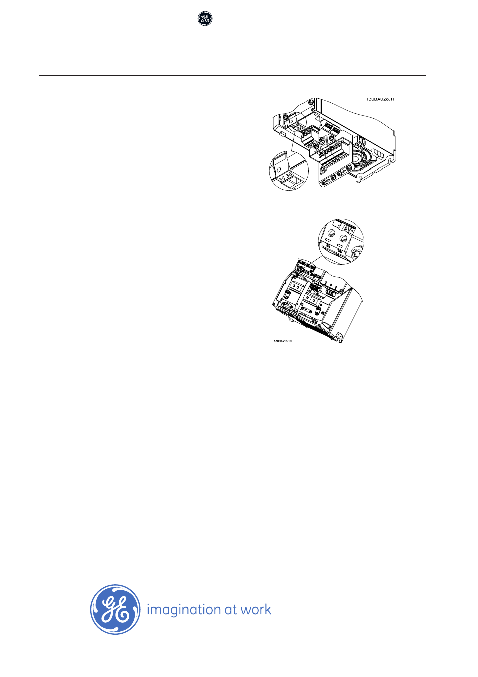
Terminal numbers:
Terminal 35: - external 24 V DC supply
Terminal 36: + external 24 V DC supply
Follow these steps:
1.
Remove the Keypad or Blind Cover
2.
Remove the Terminal Cover
3.
Remove the Cable Decoupling Plate and the
plastic cover underneath
4.
Insert the 24 V DC Back-up External Supply
Option in the Option Slot
5.
Mount the Cable Decoupling Plate
6.
Attach the Terminal Cover and the Keypad
or Blind Cover.
When 24 V External Supply option is supplying
the control circuit, the internal 24 V supply is
automatically disconnected.
Connection to 24 V External supply on Unit Sizes 12
and 13.
Connection to 24 V External supply on Unit Sizes 15,
21, 22, 31, 32 and above.