GE Industrial Solutions Spectra Series Power Panelboards AMCB6FJ, AMCB3FJ, AMCB2FJ, and AMCB4FJ User Manual
Spectra series™ power panelboards, General, Installation
g
Spectra Series™ Power Panelboards
Bolt-On Circuit Breaker Kits
WARNING:
Danger of electrical shock or injury.
Turn
OFF power ahead of the panelboard or
switchboard before working inside the
equipment or removing any component
.
Do
not remove circuit protective devices or any
other component until the power is turned
OFF.
General
These instructions apply to the following catalog numbers:
•Bolt-on circuit breaker kits AMCB6FJ, AMCB3FJ,
AMCB2FJ, and AMCB4FJ
•Circuit breaker types SFH, SFL, SFP, TF, a nd TH
•Circuit breaker cover kits AFP3SFS, AFP3SFD,
AFP3TFS, and AFP3TFD
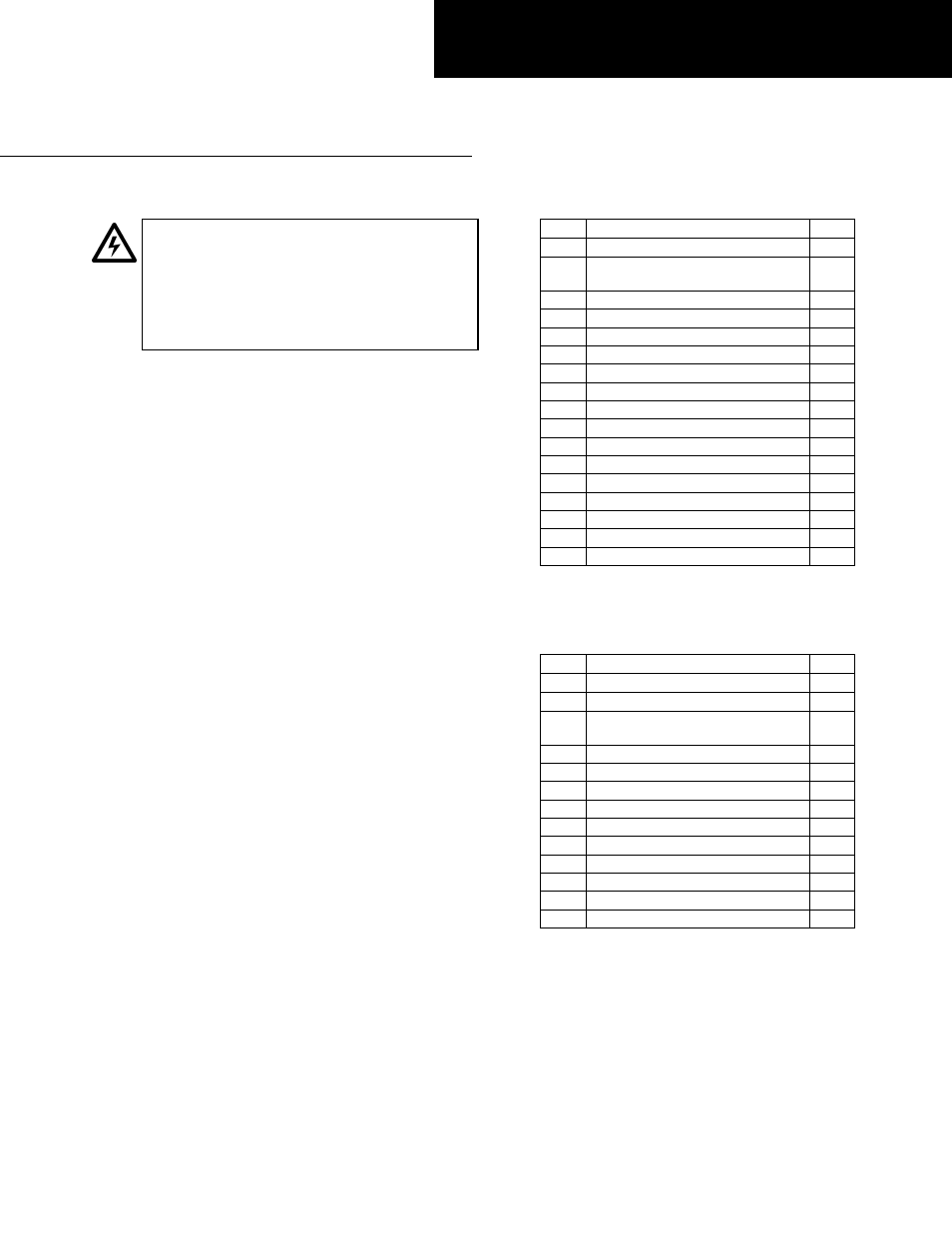
Table 1 lists the parts included in the bolt-on circuit
breaker kits for main and single-branch configurations.
Table 2 lists the parts included in the kits for double-
branch configurations. The replacement hardware kit has
catalog number AHKBF1.
Installation
Numbers in brackets in the following instructions and
figures refer to the Item numbers in Tables 1 and 2.
1. Install the circuit breaker straps.
Before installing into
Spectra APNB bolt-on–style interiors, locate the side of
the panel interior at which the dimension from the
nearest vertical bus face to the inner face of the bus
support rail is 2.75 inches, as illustrated in Figures 2
and 5. Mount the straps on this side of the vertical
bus.
a. Main and single-branch breakers.
Install the circuit
breaker straps beginning with the outermost poles,
as shown in Figures 1 and 3. Slide an antiturn clip
[16] over the square shank of a carriage bolt [2].
Insert the carriage bolt assembly into the front
square hole so that the pin rests on top of the
vertical bus.
For a right-hand cable connection, align the
square hole in the strap [1] with the carriage bolt
[2] and slide it against the vertical bus, so that the
pin on the antiturn clip [16] is inserted into the
small hole on the strap, as shown in Figure 1.
For a left-hand cable connection, position the strap
[1] and the spacer [17] so that the square hole and
hole above are aligned, then insert the carriage
bolt [2] and antiturn clip [16] so that the pin of
the clip is inserted into the small hole in the strap
and spacer, as shown in Figure 3.
Item Description
Qty.
1
A pole strap
1
2
1
/
4
-20 x 1.50 carriage bolt
1
/
4
-20 x 1.00 carriage bolt*
6
3
1
/
4
" Belleville washer
6
4
1
/
4
-20 nut
6
5
B pole strap
1
6
C pole strap
1
7
Breaker mounting bracket
1
8
Breaker mounting bracket
1
9
Thread-forming screw
4
10
1
/
4
-20 x
3
/
4
" machine screw
3
11
1
/
4
" Belleville washer
3
12
#10-32 x 3
3
/
4
" machine screw
2
13
#10 flat washer
2
14
#10-32 x
1
/
2
" machine screw
2
15
#10 lock washer
2
16
Antiturn clip
6
17
Strap spacer
3
* Use with single breaker straps connected to a
vertical bus rated at 600 A or less.
Table 1. Bolt-on breaker kit parts for main and single-branch
configurations.
Item Description
Qty.
18
A & C pole outer strap
2
19
A & C pole inner strap
2
20
/
4
-20 x 1.50 carriage bolt
1
/
4
-20 x 1.00 carriage bolt*
3
21
1
/
4
" Belleville washer
3
22
1
/
4
-20 nut
3
23
B pole strap
2
24
Breaker mounting bracket
2
25
Thread-forming screw
4
26
1
/
4
-20 x
3
/
4
" machine screw
6
27
1
/
4
" Belleville washer
6
28
#10-32 x 3
3
/
4
" machine screw
4
29
#10 flat washer
4
30
Antiturn clip
3
* Use with single breaker straps connected to a
vertical bus rated at 600 A or less.
Table 2. Bolt-on breaker kit parts for double-branch configurations.
Secure the complete strap assembly to the vertical
bus with the Belleville washer [3] and nut [4].
Leave the connection finger tight at this time.
Repeat the process on the center-pole strap [5] and
then install the last strap [6], as shown in Figure 1
or Figure 3.
DEH059 Installation Instructions
R02