GE Industrial Solutions Commercial Metering Switchboards Splicing and joining sections User Manual
Installation
DEH41036 Installation Instructions
R01
g
Commercial Metering Switchboards
Splicing and joining sections
Application
These instructions are provided for the installation of
splice bars, and to join switchboard sections at the
installation site for ease of installation. These steps must
be performed prior to setting the switchboard sections on
the final pad and termination of cables.
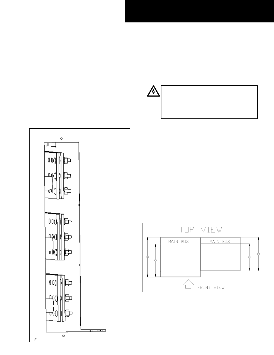
1. Check installed hardware. Make sure hardware is
installed at the end of the bus bar on each section as
shown in the picture in below:
Installation
WARNING: Danger of electrical shock or injury.
Turn
OFF
power ahead of the switchboard
before working inside the equipment or
removing any component
.
Equipment is to be
installed and maintained by properly trained
and qualified personnel only.
eep in mind this hardware is loose and is held to
2. Check splice dimensions. Compare the dimensions of
the picture above the first section is 5” deeper then
K
the bus by a rubber band. To avoid losing any
hardware, do not remove the rubber band until the
splice bars are going to be installed. The splice bars
are located in the Section marked with the yellow
label “ Splices in this section.”
the bus against the splice bars to ensure the 2 sections
are going to be joined successfully. First, measure
from the front of each section to the horizontal bus,
then subtract the distance of the first sections from
the second. This should be equal to the length of the
splice bars.
In
the second one, and the main bus is located an equal
distance from the rear. Therefore flat bus splices are
required.