GE Industrial Solutions Spectra Series Power Panelboards Circuit Breaker Mounting Hardware Kits User Manual
General, Installation, Attention – procedure for aluminum terminations
g
Spectra Series™ Power Panelboards
Circuit Breaker Mounting Hardware Kits
WARNING:
Danger of electrical shock or injury.
Turn
OFF power ahead of the panelboard or
switchboard before working inside the
equipment or removing any component
.
Do
not remove circuit protective devices or any
other component until the power is turned
OFF.
General
These instructions apply to circuit breaker mounting
hardware kits with catalog numbers AHKE1, AHKEL1,
AHKF1, AHKG1, AHKJ1, AHKLB1, and AHKQ1.
Installation
1. Prepare the module.
Remove the side trim and filler
plate from the new circuit breaker position, as shown
in Figure 1. Remove the protective caps or insulating
tape from the tops of the line end posts and discard.
2. Install the circuit breaker.
Remove the lug cover(s) on
the circuit breaker, if present, but do not discard. Place
the
ON
side of the breaker over the stud posts and
resting on the load-end mounting bracket. Tighten
the line- and load-end mounting screws according to
Table 1. Replace the lug cover(s) on the circuit
breaker.
NOTE:
On J-Frame breakers only, the line-
mounting screws are replaced with
5
/
16
-18 nut-
washer assemblies.
3. Wiring the circuits.
Refer to the rating label on the
circuit breaker for the proper tightening torque levels.
4. Reinstall the filler plate and side trim.
Remove the
breaker plug cap(s) from the filler plate and reinstall
on the module. Reinstall the side trim plate(s).
Attention – Procedure for Aluminum
Terminations
1.
Strip the insulation, being careful to not nick the wire.
2.
Clean the wire strands with a wire brush.
3.
Thoroughly coat the stripped conductor with a
suitable antioxidant compound, such as ALNOX or
PENETROX A13.
4.
Insert the conductor and tighten the connector screw
to the torque indicated on the rating label.
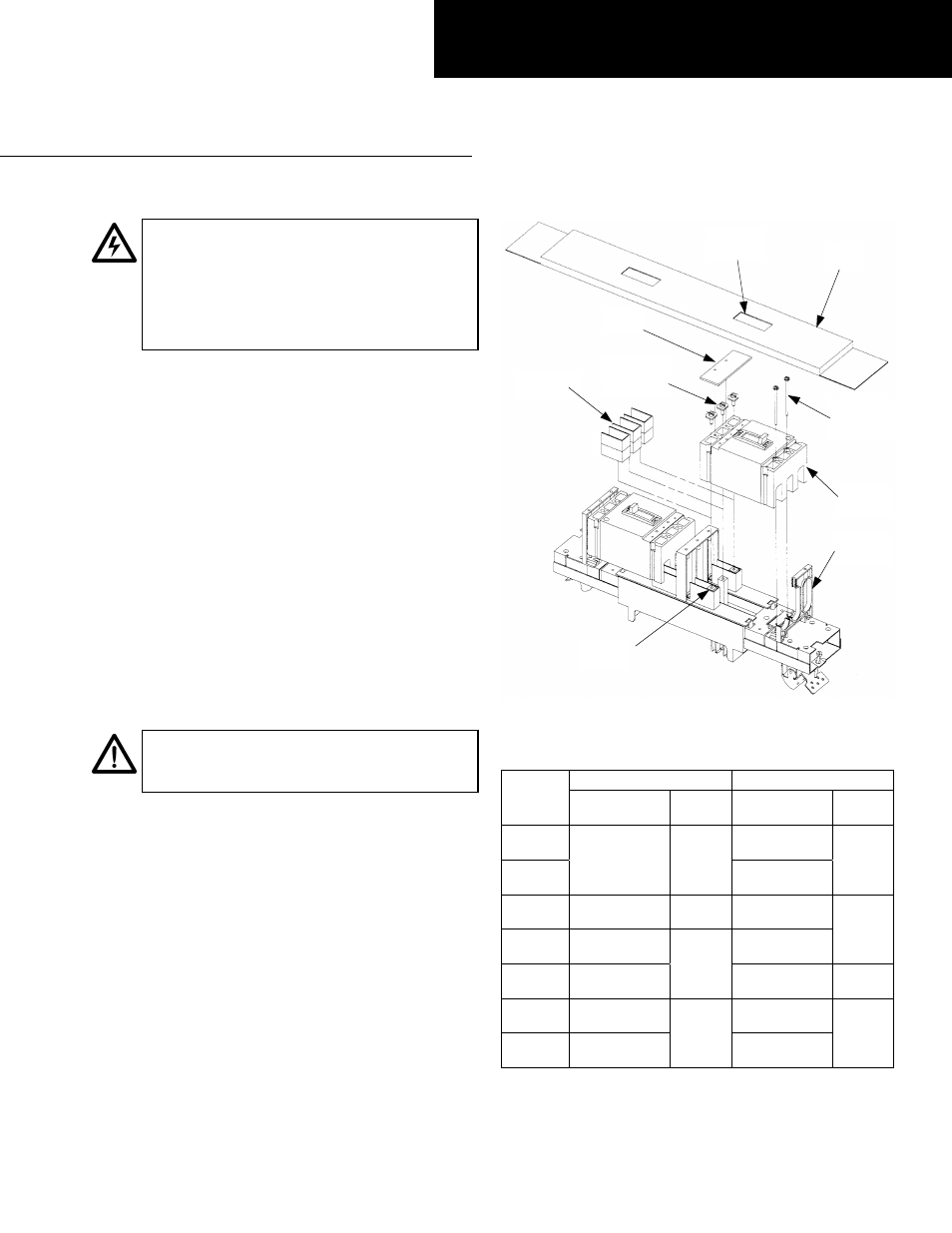
Figure 1. Typical circuit breaker module. (Your specific module
configuration may not appear as shown.)
Line-End Mtg. Screw
Load-End Mtg. Screw
Cat. No.
Description
Torque
(in.-lbs.)
Description
Torque
(in.-lbs.)
AHKE1
#8-32 x 2
3
/
4
"
round head
AHKEL1
#10-32 x
1
/
2
"
pan head
27–32
#8-32 x 2
1
/
2
"
round head
16–20
AHKF1
1
/
4
-20 x
3
/
4
"
hex head
40–50
#10-32 x 3
3
/
4
"
pan head
AHKG1
5
/
16
-18 x 1"
hex head
#10-32 x 3"
round head
27–32
AHKJ1
5
/
16
-18 hex
nut
70–110
1
/
4
-20 x 1
1
/
2
"
round head
40–50
AHKLB1
1
/
4
-20 x 1"
socket head
#10-32 x 2
3
/
4
"
pan head
AHKQ1
1
/
4
-20 x
3
/
4
"
round head
40–50
#10-32 x 2
3
/
4
"
round head
27–32
Table 1. Tightening torque levels for the mounting screws in the
hardware kits.
GEH5913 Installation Instructions
R02
Breaker
Plug Cap
Filler
Plate
Lug
Cover
Line-End
Mounting
Screws
Load-End
Mounting
Screws
Circuit
Breaker
Mounting
Bracket
Stud
Posts
Protective
Caps