GE Industrial Solutions Spectra Series Power Panelboards AMC3KM and AMC2KM User Manual
Spectra series™ power panelboards, General, Installation
g
Spectra Series™ Power Panelboards
Circuit Breakers and Modules
WARNING:
Danger of electrical shock or injury.
Turn
OFF power ahead of the panelboard or
switchboard before working inside the
equipment or removing any component
.
Do
not remove circuit protective devices or any
other component until the power is turned
OFF.
General
These instructions apply to the following catalog numbers:
•Circuit breaker modules AMC3KM and AMC2KM
•Circuit breaker frames TKM, THKM, TK4V, TKL4V,
SKHA, SKLA, and SKPA
Installation
1. Phase balancing for two-pole devices in three-phase
systems.
To balance the panelboard load, remove the
screws on the appropriate bus clip, reposition the bus
clip as shown in Figure 1, then install and tighten the
screws to 27–32 in-lb.
Figure 1. Repositioning the bus clip to balance the load.
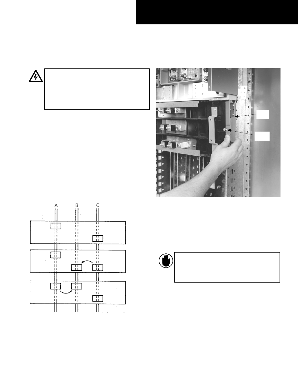
2. Prepare the breaker module.
Loosen the latch lock
screws and fully retract the rail latches. Line up the
guide fingers on both ends of the module with the
notches in the panelboard interior rails, as shown in
Figure 2.
Figure 2. Preparing the circuit breaker module for installation.
3. Install the module.
Latch one side of the circuit
breaker module. Release the rail latch. Pivot the
module onto the bus bars and engage the second
latch. Release the rail latch. Tighten the rail latch
screws to 25 in-lb as shown in Figure 3. Allow no space
between units except as noted for type SKPA circuit
breakers in the Caution below.
CAUTION:
When a type SKPA circuit breaker is
to be mounted on a module adjacent to an ADS
switch, leave a 1X (1
3
/
8
") space between the
units. Use an APP1W panel filler plate to close
the opening.
GEH5623 Installation Instructions
R04
A & C Phase
As Received
A & B Phase
B & C Phase
Latch
Screw
Rail
Latch