Warning, Spd display panel – GE Industrial Solutions GE A-Series 9îand 24î Panel Box User Manual
Page 13
2020000604 (12/09) Page 13 of 15
OPERATION:
After applying power to the SPD, verify that the protection monitoring circuits are functioning
correctly. If all status alarms indicate “normal”, the SPD has been successfully installed and is
operational.
1.
LINE STATUS INDICATOR LEDs
The green line status LED’s provide visual indication of SPD health status. As long as the SPD
is connected to the electrical system supply voltage and the SPD suppression circuitry is
functional, the line status indicators will be illuminated green. There is one green indicator
per each protected phase.
2.
ALARM STATUS INDICATOR LEDs
When illuminated, the red Alarm Status Indicator LED will provide notification of a SPD failure
condition. Verify the Alarm Status Indicator is not illuminated upon startup.
3.
REMOTE ALARM CONTACTS
Remote Alarm Contacts are available to remotely monitor the health status of the SPD. An
alarm condition will result in a status change of the contacts. These contacts do not affect
WARNING
UPON ENERGIZATION OF THE SPD, IF ANY OF THE LAMPS OR ALARMS
INDICATES AN ABNORMAL CONDITION, POWER SHOULD PROMPTLY BE
DISCONNECTED FROM THE SPD. THE ELECTRICAL SYSTEM SHOULD BE
INSPECTED
AND
THE
PRE-INSTALLATION
REQUIREMENTS
SHOULD
BE
VALIDATED. DO NOT ATTEMPT TO LEAVE POWER APPLIED TO THE SPD, OR RE-
ENERGIZE THE SPD IN THE EVENT OF AN ALARM CONDITION. PLEASE
CONTACT YOUR LOCAL GE REPRESENTATIVE FOR FURTHER ASSISTANCE.
0
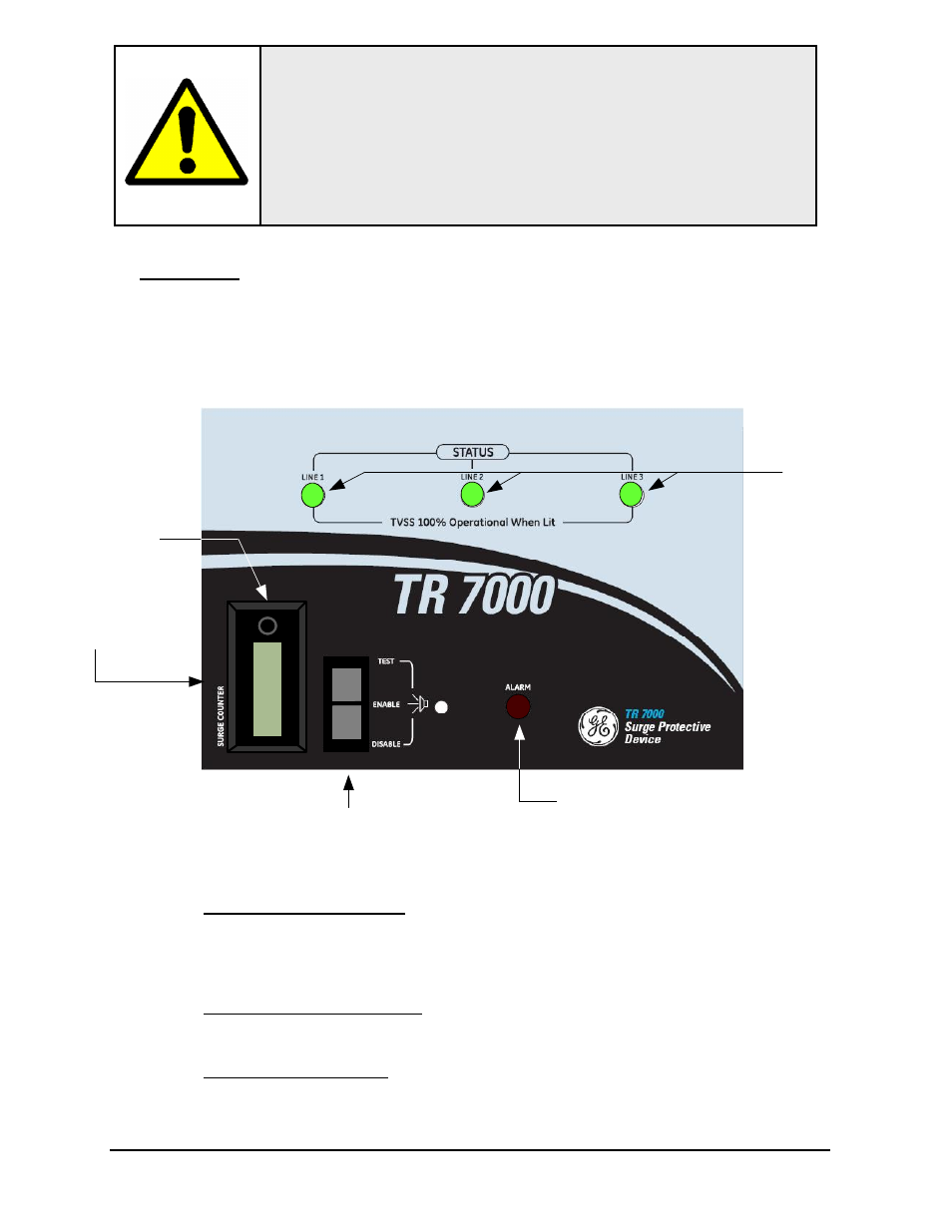
SPD Display Panel
Surge Counter
Reset Button
Surge Counter
LCD Display
Test / Enable /
Disable Switch
Alarm
Indicator LED
Line Status
Indicator LEDs