Panels with full-height door fronts, After installing the interior, Attention – procedure for aluminum terminations – GE Industrial Solutions Spectra Series Power Panelboards APN and APNB User Manual
Page 2
Panels with Full-Height Door Fronts
6. If a full-height door front is to be used on the panel, it is
necessary to reinstall the deadfront once the wiring has
been brought into the panel. (These instructions are also
provided with the door front.)
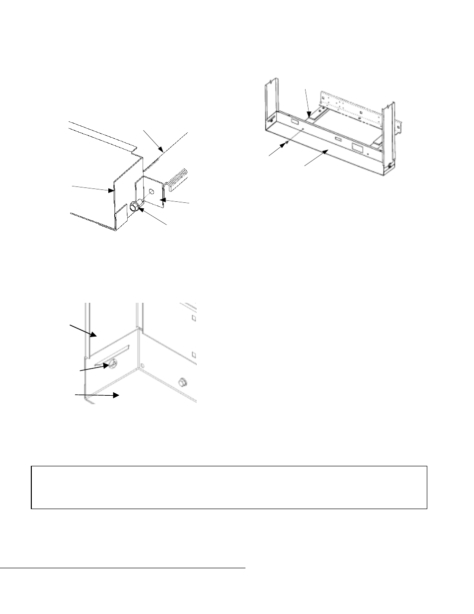
27- and 31-inch-wide panels. To replace or install the
deadfront, first install the top and bottom ends to the
mounting post, as shown in Figure 5. Tighten the
1
/
4
-20
hex-head screws to 50–60 in-lb.
Figure 5. Installing the ends to the mounting post.
27–44-inch-wide panels. Fasten the end filler plates to the
side plates with the
1
/
4
-turn fasteners shown in Figure 6.
The end filler plate with labeling attached must be placed
at the load end of the panel, opposite to the incoming
power.
Figure 6. Fastening the end filler to the side plate.
36–44-inch-wide panels. Refasten the end fillers to the
mounting posts, tightening the
1
/
4
-20 screws to 50–60 in-lb,
as shown in Figure 7. The end filler plate with labeling
attached must be placed at the load end of the panel,
opposite to the incoming power.
Figure 7. Fastening the end fillers to the mounting posts.
After Installing the Interior
Do not discard the remaining contents of the bag that contained
these instructions. The circuit identification tabs should be
used, as applicable, at the time the circuit protective devices are
installed. The NEMA instruction sheet provided should be
retained for use by maintenance personnel.
If plug-in devices are used, the area above the device-mounting
latches should be kept clear of any wires running through the
side gutters. This facilitates the future removal of a device, if
necessary.
Attention – Procedure for Aluminum
Terminations
1. Strip the insulation, being careful to not nick the wire.
2. Clean the wire strands with a wire brush.
3. Thoroughly coat the stripped conductor with a suitable
antioxidant compound, such as ALNOX or PENETROX
A13.
4. Insert the conductor and tighten the connector screw to the
required torque, as indicated on the rating label.
g
GE Industrial Systems
General Electric Company
41 Woodford Ave., Plainville, CT 06062
GEH5589 R07 0501
© 2001 General Electric Company
These instructions do not cover all details or variations in equipment nor do they provide for every possible contingency that
may be met in connection with installation, operation, or maintenance. Should further information be desired or should
particular problems arise that are not covered sufficiently for the purchaser’s purposes, the matter should be referred to the
GE Company.
End
Filler
Mounting
Post
Welded
Bracket
1
/
4
-20
Screw
Side
Plate
End
Filler
1
/
4
-Turn
Fastener
Mounting
Post
End
Filler
1
/
4
-20
Screw