Operation, Outputs, Daylight optimization module configuration – GE Industrial Solutions A Series Lighting Control Panelboards ASRGLCDOK User Manual
Page 3: Mapping the inputs
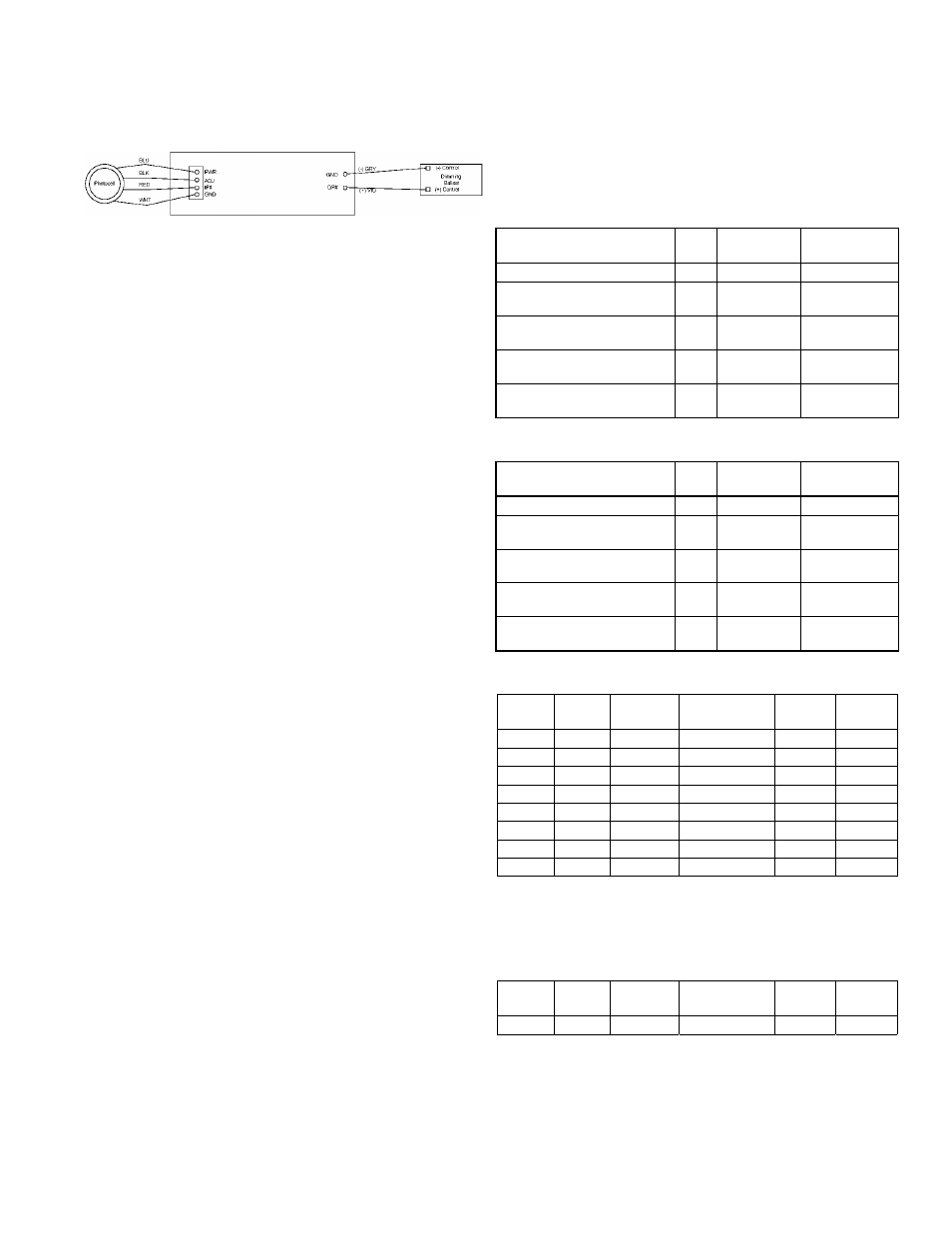
The inputs on the Daylight Optimization Module are
designed specifically for GE indoor photodiodes, catalog
number RPESN-IN.
Figure 3. Input and output connections to the Daylight Optimization Module.
Outputs
The Daylight Optimization Module has eight 1 V to 10 V
outputs, connected as illustrated in Figure 3 to dimming
ballasts drawing less than 0.5 mA. Each Daylight
Optimization Module output channel can sink up to 25
mA of current, supporting up to 50 dimming ballasts. A
single Daylight Optimization Module can control up to
400 ballasts.
Daylight Optimization Module Configuration
Each input to the Daylight Optimization Module controls
a corresponding output in a proportional-integral (PI)
feedback loop. The eight inputs (IP1 to IP8) and eight
outputs (OP1 to OP8) comprise the eight feedback loops
on the Module.
The eight sensitivity potentiometers on the Daylight
Optimization Module (indicated in Figure 2) are used to
calibrate the gain of the photodiode connection to the
given input channel.
Operation
This section describes the operation of the Daylight
Optimization Module.
Mapping the Inputs
The Daylight Optimization Module has two types of
objects, analog input (AI) and analog variable (AV). This
section describes how to map the functional objects from
the master device (Lighting Controller) database to the
Module.
Inputs (AI601 to AI608 and AI701 to AI708) – The analog
input objects are read-only and gather voltage values from
a photodiode input.
Setpoint Variables (AV601 to AV608 and AV701 to AV708) –
These variables define the desired amount of light for the
feedback channel. The setpoint value can be edited with
the Handheld Programmer.
Proportional Band (AV609 to AV616 and AV709 to AV716)
and Reset Rate (AV617 to AV624 and AV717 to AV724)
Variables – These variables control the proportional and
integral properties of the individual proportional-integral
(PI) feedback loops. These values should be treated as
read-only unless you have detailed knowledge of (PI)
feedback systems.
Outputs
– Analog variable objects (AV625 to AV632 and
AV725 to AV732) are read-only objects that display the
voltage delivered to the dimming ballasts.
The ranges of objects for the first and second Daylight
Optimization Module connected to a Lighting Controller
are listed in Table 1 and Table 2. Object offsets for the
dimming circuit are listed in Table 3.
Description
Type
BACnet
Object
Modbus
Register
Lighting Levels [0–100]
RO
AI601–608
Fn 4, 117–124
Lighting SP (set point)
[0–100]
RW
AV601–608
—
Lighting Proportional
Band [0–200?]
RO
AV609–616
—
Lighting Reset Rate
(internal usage)
RO
AV617–624
—
Lighting Output (8
outputs)
RO
AV625–632
—
Table 1. Object ranges for the first Daylight Optimization Module.
Description
Type
BACnet
Object
Modbus
Register
Lighting Levels [0–100]
RO
AI701–708
Fn 4, 133–140
Lighting SP (set point)
[0–100]
RW
AV701–708
—
Lighting Proportional
Band [0–200?]
RO
AV709–716
—
Lighting Reset Rate
(internal usage)
RO
AV717–724
—
Lighting Output (8
outputs)
RO
AV725–732
—
Table 2. Object ranges for the second Daylight Optimization Module.
Loop # Input #
Setpoint
AV
Proportional
Band AV
Reset
Rate AV
Output
AV
1
1
1
9
17
25
2
2
2
10
18
26
3
3
3
11
19
27
4
4
4
12
20
28
5
5
5
13
21
29
6
6
6
14
22
30
7
7
7
15
23
31
8
8
8
16
24
32
Table 3. Object offsets for the Daylight Optimization Module dimming circuit.
Example – For Daylight Optimization Module 1 addressed
as 6, the objects related to control circuit 1 are as listed in
Table 4.
Loop # Input #
Setpoint
AV
Proportional
Band AV
Reset
Rate AV
Output
AV
2
AI602
AV602
AV610
AV618
AV626
Table 4. Control circuit objects for example.