12v austinlynx, 10a: non-isolated dc-dc power modules,programmable, Data sheet – GE Industrial Solutions 12V AustinLynx 10A User Manual
Page 13: Feature descriptions
GE
Data Sheet
12V AustinLynx
TM
10A: Non-Isolated DC-DC Power Modules,Programmable
10Vdc –14Vdc input; 0.75Vdc to 5.5Vdc output; 10A Output Current
May 8, 2013
©2013 General Electric Company. All rights reserved.
Page 13
Feature Descriptions
(continued)
By using a 1% tolerance trim resistor, set point tolerance of
±2% is achieved as specified in the electrical specification. The
POL Programming Tool, available at
www.lineagepower.com
under the Design Tools section, helps determine the required
external trim resistor needed for a specific output voltage.
The amount of power delivered by the module is defined as the
voltage at the output terminals multiplied by the output current.
When using the trim feature, the output voltage of the module
can be increased, which at the same output current would
increase the power output of the module. Care should be taken
to ensure that the maximum output power of the module
remains at or below the maximum rated power (P
max
= V
o,set
x
I
o,max
).
Remote Sense
The 12V Austin Lynx Programmable SMT power modules have a
Remote Sense feature to minimize the effects of distribution
losses by regulating the voltage at the Remote Sense and GND
pins (See Figure 29). The voltage between the Sense pin and Vo
pin must not exceed 0.5V. Although both the Remote Sense
and the TRIM features can increase the output voltage Vo, the
maximum increase is not the sum of both. The maximum Vo
increase is the larger of either the Remote Sense or TRIM.
The amount of power delivered by the module is defined as the
output voltage multiplied by the output current (Vo x Io). When
using Remote Sense and/or TRIM, the output voltage of the
module can increase, which if the same output is maintained,
increases the power output by the module. Make sure that the
maximum output power of the module remains at or below the
maximum rated power. When the Remote Sense feature is not
being used, leave the Remote Sense pin unconnected.
V
O
COM
V
IN
(+)
COM
R
LOAD
R
contact
R
distribution
R
contact
R
distribution
R
contact
R
contact
R
distribution
R
distribution
Sense
Figure 29. Remote sense circuit configuration
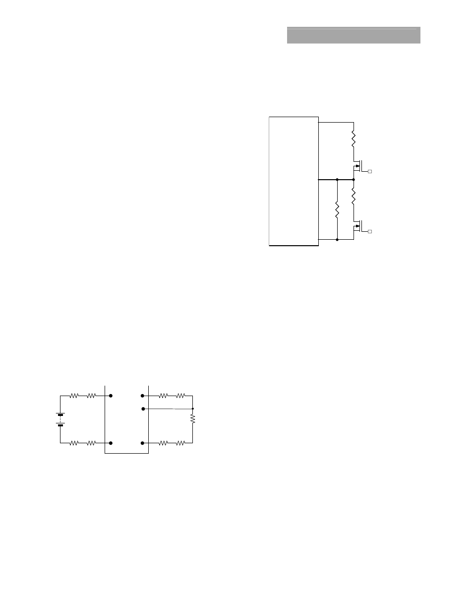
Voltage Margining
Output voltage margining can be implemented in the 12V
Austin Lynx Programmable SMT modules by connecting a
resistor, R
margin-up
, from Trim pin to ground pin for margining-
up the output voltage and by connecting a resistor, R
margin-
down
, from Trim pin to Output pin. Figure 30 shows the circuit
configuration for output voltage margining. The POL
Programming Tool, available at
www.lineagepower.com
under the Design Tools section, also calculates the values of
R
margin-up
and R
margin-down
for a specific output voltage and %
margin. Please consult your local GE technical
representative for additional details
Vo
Austin Lynx or
Lynx II Series
GND
Trim
Q1
Rtrim
Rmargin-up
Q2
Rmargin-down
Figure 30. Circuit Configuration for margining Output
voltage.