GE Industrial Solutions MicroVersaTrip Plus and MicroVersaTrip PM AK-150 User Manual
Page 3
3
SECTION 4 BACK FRAME
BREAKER CONVERSION
(CONTINUED)
Installing Phase Sensors (CT’s)
(High Range Instantaneous Kits Only)
Phase sensor installation for high range
instantaneous conversion kits is very similar to the
standard GE AK-25 or AKU-25 MicroVersaTrip
Plus and MicroVersaTrip
PM conversion kits. The
high range instantaneous conversion kits differ in
that the CT’s are supplied with an integral terminal
block and each phase sensor requires four (4)
separate electrical connections.
Phase sensor modification for the AK-25 circuit
breakers is completed by mounting the three (3)
current sensor assemblies to the back frame. See
Fig. 4-1, 4-2, and 4-3 on pages 13 and 14 of the
original installation instructions.
Step 1.
Insert the lower copper stud through the back
frame and attach it via the mounting screw.
Step 2.
Position the CT with its terminal toward the front
and top and loosely mount it to the stud with the
copper, 90
°
angled bus strap, and the bolt
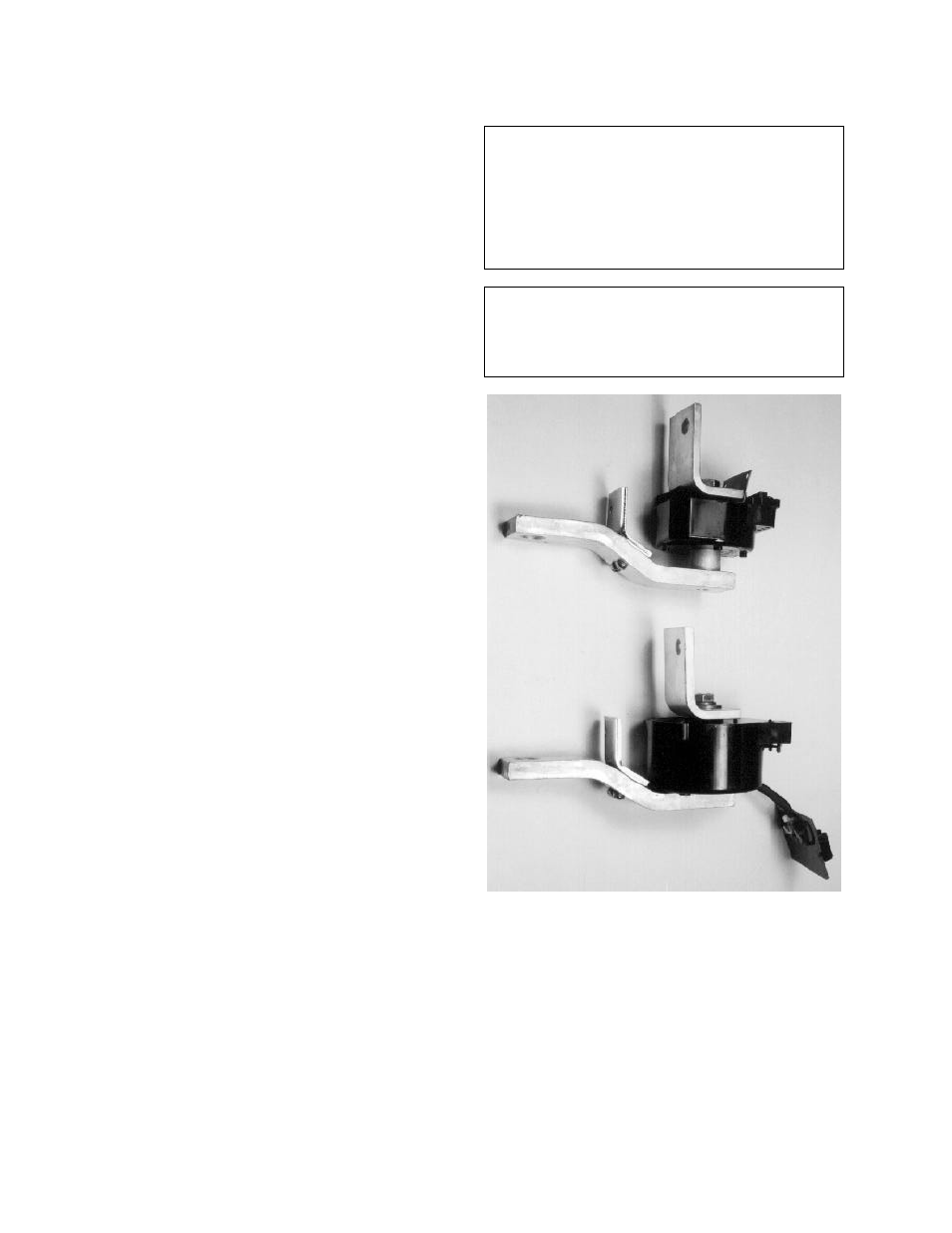
provided. Be sure to install the anti-rotation plate
during this step and that the smaller diameter of
the copper stud is towards the top of the assembly
(Fig. 4-7). Note, Fig. 4-7 depicts a high range
instantaneous CT assembly on the top and an AK-
25 CT assembly on the bottom.
Step 3.
Align the assembly, then torque the two (2) 3/8”
bolts in the strap to 250 in.-lbs. each to assure
proper contact integrity.
Step 4.
Reassemble the front and back frames.
Step 5.
The wire harness can be connected only to the
CT’s after the front and back frames have been
joined. The pair of black wire leads in the wire
harness are connected to the terminals labeled “HI
INST” on each CT. Polarity for these black leads is
not critical.
CAUTION: The wire harness for high range
instantaneous conversion kits require four (4)
separate electrical connections for each phase
sensor in lieu of the two (2) connections in a
standard GE type AK-25 conversion kit. Be sure
to connect the wire harness to the phase sensors
as shown in Fig. 8-1 of this supplementary
publication.
WARNING: FAILURE TO PROPERLY CONNECT
THE WIRE HARNESS ASSEMBLY TO THE PHASE
SENSORS MAY RESULT IN INADEQUETE
PROTECTION FROM THE PROGRAMMER AND
DAMAGE TO THE CURRENT SENSORS.
Fig. 4-7. High Range Instantaneous CT Assembly
SECTION 7 TESTING AND
TROUBLESHOOTING