Step 2 – install the breaker operating mechanism – GE Industrial Solutions Record Plus TDM, NEMA 4__4X: FE250 User Manual
Page 3
Step 2 – Install the Breaker
Operating Mechanism.
t
Dir
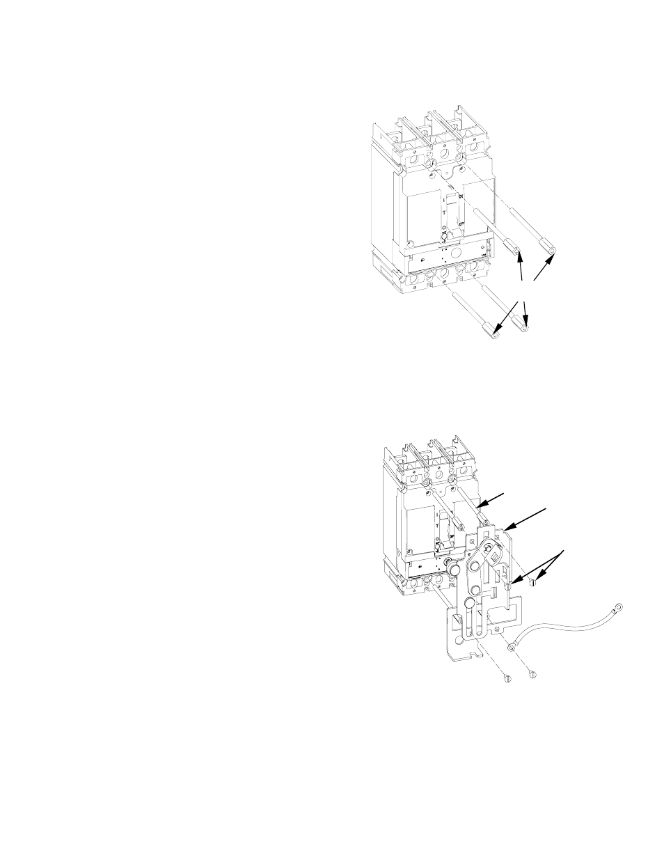
1. Move the breaker handle to the OFF position.
2. Mount the breaker to the enclosure with
#10-32 X 3 5/32 " screws [1], as illustrated in Figure 3.
Tighten he screws to 27 - 32 in-lb. Complete the
installation of the circuit breaker according to
installation instructions DEH40360.
3. FENRM2
ect Mounting -
(Refer Figure 9 for outline views of completed
installations with dimensions).
a. Place the base-crank assembly [2] on the breaker,
as illustrated in Figure 4.
b. Insert the four #10-32 x 1/2" screws [4] through
the mounting holes in the base and into the
heads of the breaker mounting screws [1], with
the grounding wire [3] attached to one of the
screws.
c. Tighten the screws to 27 - 32 in-lb. Secure the
other end of the grounding wire to a suitable
ground location.
4. FENRM4 Door Mounting- -
(Refer Figure 10 for outline views of completed
installations with dimensions).
a. Place the base-crank assembly [5] on the breaker,
as illustrated in Figure 5.
b. Place the coupler (6) on to the crank in the base
asm (5) and fasten by screw, #8-32 x 5/16" (7), as
illustrated in Figure 6. Tighten the screws to 16 -
20 in-lb
c. Measure the distance from the breaker-mounting
surface to the handle-mounting surface, H, as
shown in figures 7 & 10.
d. Cut the handle arm [8] to the length L given by
L =H –5 29/32 inch (150 mm), as illustrated in
Figure 7 & 8.
e. Attach the handle arm [8] to the coupler [6] with
#8-32 x 5/16" screws [7], as illustrated in Fig6.
Tighten the screws to 16 - 20 in-lb.
Figure 4. Mounting the FENRM2 assembly onto the
breaker
[1]
Figure 3. Mounting the breaker in the enclosure.
[1]
[2]
[4]
[3]
DEH41027