GE Industrial Solutions A Series Lighting Control Panelboards Installing Control Wire Insulation User Manual
A series, Lighting control panel boards, Installing control wire insulation
A Series
®
Lighting Control Panel boards
g
Installing Control Wire Insulation
Catalog No. Qty. Description
ASRGLCCWT 1
Control Wire Insulation Tubing
WARNING: Danger of electrical shock or injury. Turn OFF
power service to the line side of the Panel board or
switchboard before working inside the equipment or
removing any component
.
Equipment is to be installed and
maintained by properly trained and qualified personnel only.
DEH41102 Installation Instructions R01
It is a requirement per UL67 sect.18A & NEC725.55, that
low voltage class 2 & 3 control wiring be separated with
tubing having an insulation rating equal to branch load
wiring, class 1, if occupying the same wire way. In order to
comply with the above codes GE is providing this sleeving
kit. It allows compliance for control wiring with insulation
ratings below that of load wiring which runs through panel
box walls to the controller box in order to connect to the
controller.
Installation Instructions:
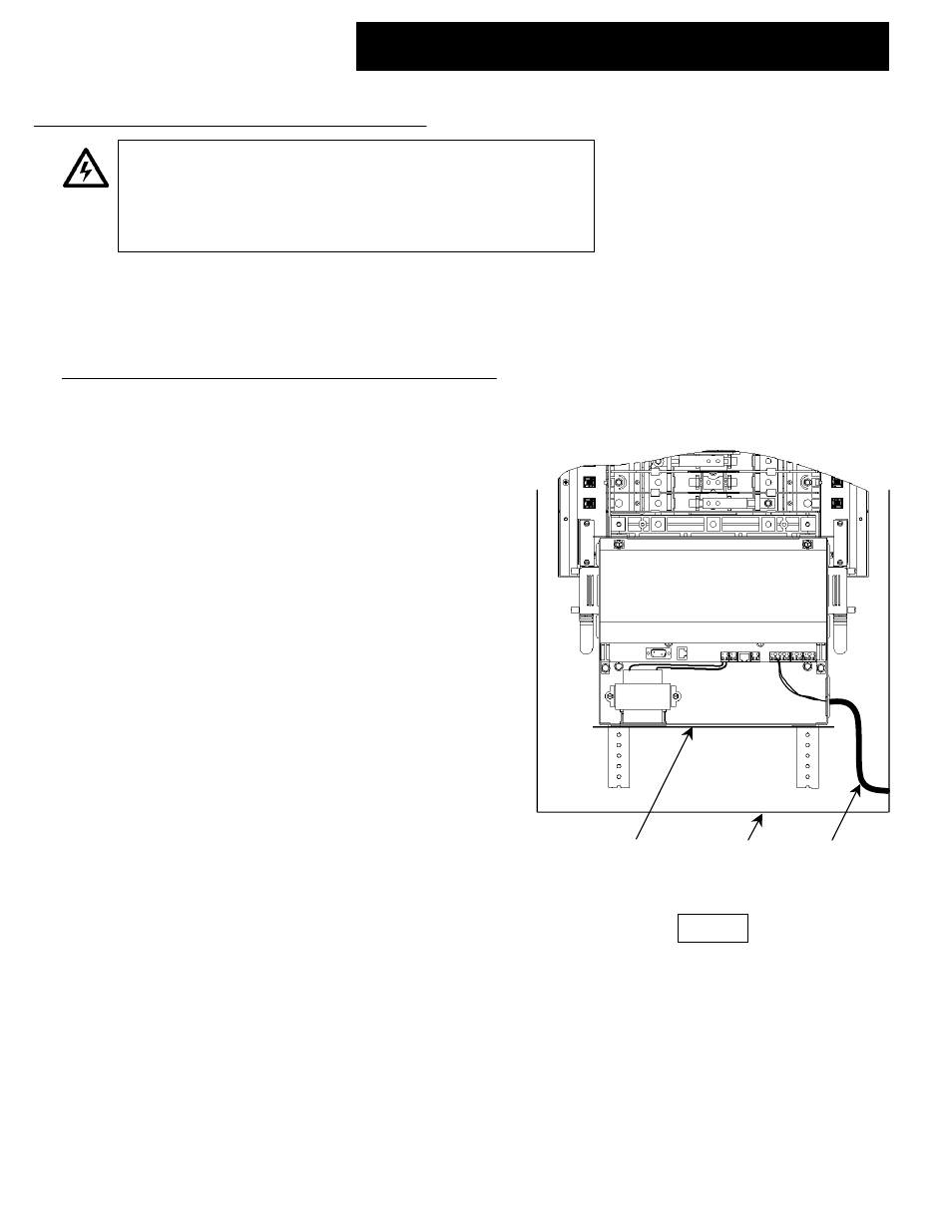
1. Size the length of routing path of control wiring through the
panel box to the controller box in fig 1.
2. Cut length of tubing provided equal to that of routing path
plus 2 inches. Tubing provided is 600V rated .
3. Slide the control wiring through the shrink tubing and
position tubing for overlap going beyond sheet metal walls
in both panel box and controller box.
4. Use wire nuts (2) for clamping and strain relieving control
wire passing through the holes in the sheet metal. Hole
size provided in the control box is 7/8 inch dia. Sized for ½
inch nuts. Wire nuts not provided.
5. Tighten down screw clamp on wire nuts if provided to
secure control wire and shrink tubing.
CONTROL
WIRE
INSULATING
TUBING
PANEL
BOX
CONTROLLER
BOX
FIG 1
GE Consumer & Industrial General Electric Company, Plainville, CT 06062
2004 General Electric Company
DEH41102 R01