GE Industrial Solutions TT series User Manual
Installation & operation manual, Ge energy digital energy, Tt series surge protective device
ᎆᓻᜂᇿൻࣹΥ႐
Clear window = Normal Operation
ጱᓻᜂᇿࣚፚଆۅ
Red window replacement required
Normal Operation
ࣹᤙᛸ
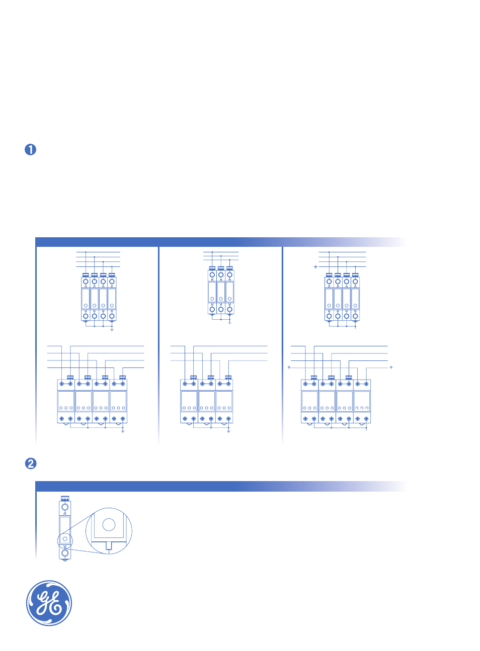
Single Pole or Multi Pole
TNS System
TNC & IT System
TT System
L1
L2
L3
N
4Pଣፊน
N
L1
L2
L3
3P+Nଣፊน
4Pଣፊน
L1
L2
L3
N
L1
L2
L3
N
3P+Nଣፊน
L1
L2
L3
3Pଣፊน
L1
L2
L3
L1
L2
L3
3Pଣፊน
GE Energy
Digital Energy
Installation & Operation Manual
ᇏࠗൻᇏᄡᤣଣௌे֮ፊႚԤ
ڦᶙଥᕲݏVSGᝒೂᶇ˗ݏ̝73Dᶈ
ᤣଣࡅፊᅇॶ9pp2058pp2
ঐᮣࠎᜠPFE--ྔٿϋધ
Verify Correct Connection and Line Voltage
Diagram : Recommended to maximize the
SPD* performance ( up to 40A )
Connector lugs sized for wire range 6 mm2-25 mm2
ଣፊኂ߬ઌҾᆕ7Q-p
Torque value of the terminal screws 4N*m
Backup protection MCB** or fuse must be installed
SPD: 20 kA
SPD: 45 kA
SPD: 65 kA
SPD: 80 kA
SPD: 100 kA
MCB: 16 A type B ”preferred”
MCB: 20 A type B ”preferred”
MCB: 32 A type B ”preferred”or C
MCB: 40 A type B ”preferred”
MCB: 63 A type B ”preferred”
TT series Surge Protective Device
(SPD)
GB
Recognized
DIN R
ail Mount
L1
L2
L3
L1
L2
L3
N