GE Industrial Solutions EntelliGuard G Auxiliary Switch User Manual
Entelliguard, G circuit breaker, Accessories
Introduction
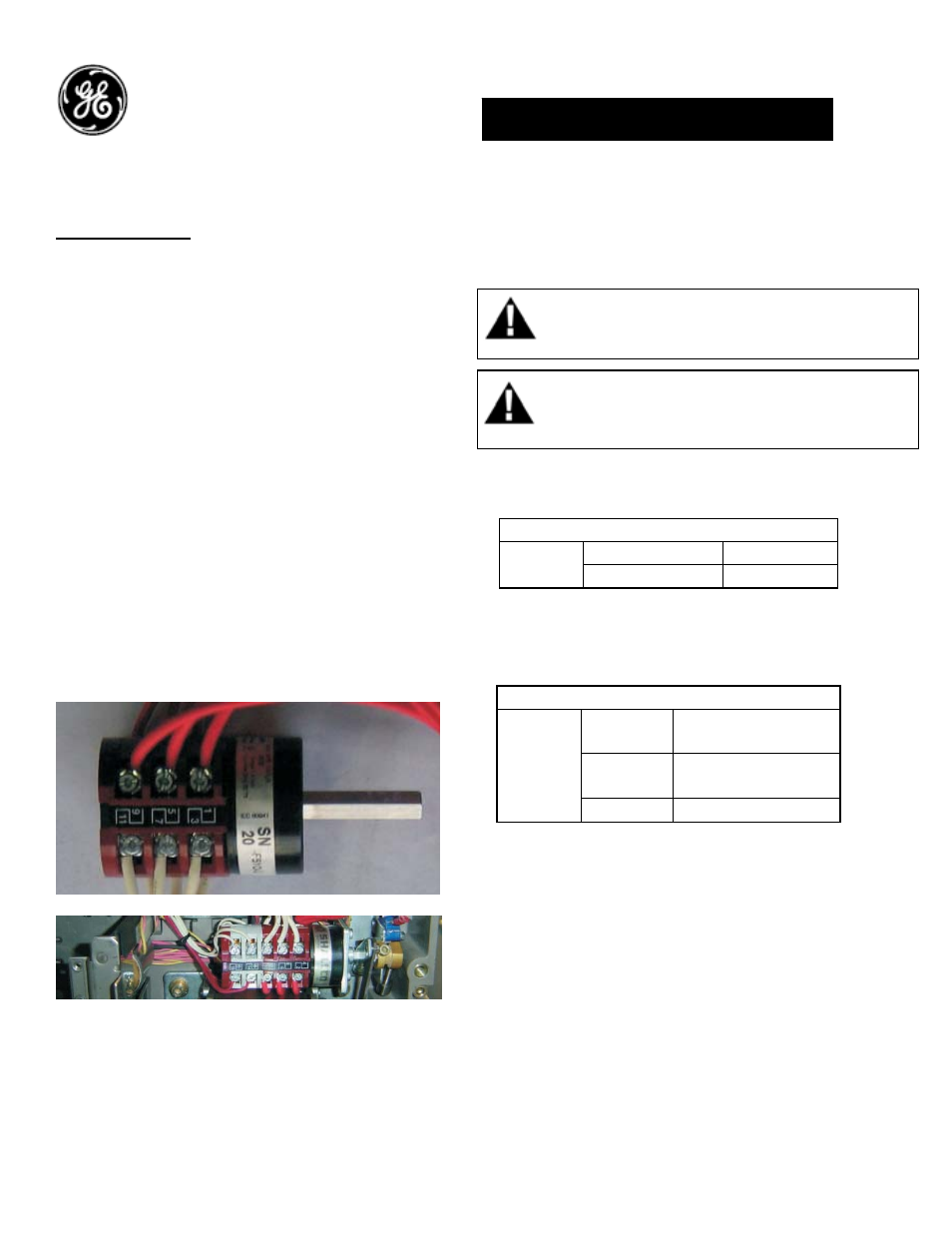
Auxiliary Switch:
Auxiliary contacts indicate the position of the
Circuit Breaker main contacts. These contacts
operate simultaneously with the breakers main
contacts. Default breaker configuration consists
of 3 normally open (NO) and 3 normally closed
(NC) contacts. The STD Auxiliary switch (GAUX3R)
can be replaced with any of the following
configurations to increase the number of
available contacts.
• Power rated contacts 8 NO & 8 NC
(GAUX6R)
• Power rated contacts 3 NO & 3 NC plus
Low Signal rated contacts 2 NO & 2 NC
(GAUX5R)
• Power rated contacts 4 NO & 4 NC plus
Low Signal rated contacts 4 NO & 4 NC
(GAUX8R)
See Wiring Diagram on last page for Power Rated
and Low Signal Connections
DEH-41415 Installation Instructions
EntelliGuard
®
G Circuit Breaker
Accessories
Auxiliary Switch
WARNING: Before installing any accessories, turn the
breaker OFF, disconnect it from all voltage sources,
and discharge the closing spings.
AVERTISSEMENT: Avant d’installer tout accessoire,
mettre le disjoncteur en position OFF, le déconnecter
de toute tension d’alimentation , et décharger les
resorts d’armement
Table 1. Auxiliary switch ratings
DC Ratings*
240V
5A (6 contacts in
series)
125V
10A (3 contacts in
series)
DC
24V 15A
* DC ratings are not UL listed
Note:
The following Aux options are not available when
a Side Mounted Disconnect or Coil Signaling
Contacts are installed in the breaker
• Power rated contacts 4 NO & 4 NC plus
Low Signal rated contacts 4 NO & 4 NC
(GAUX8R)
Power rated contacts 8 NO & 8 NC (GAUX6R)
AC Ratings
220/240V
10A
AC
110/120V
15A
1