GE Industrial Solutions Spectra Series Power Panelboards Bolt-On Main Lug Kits User Manual
Page 2
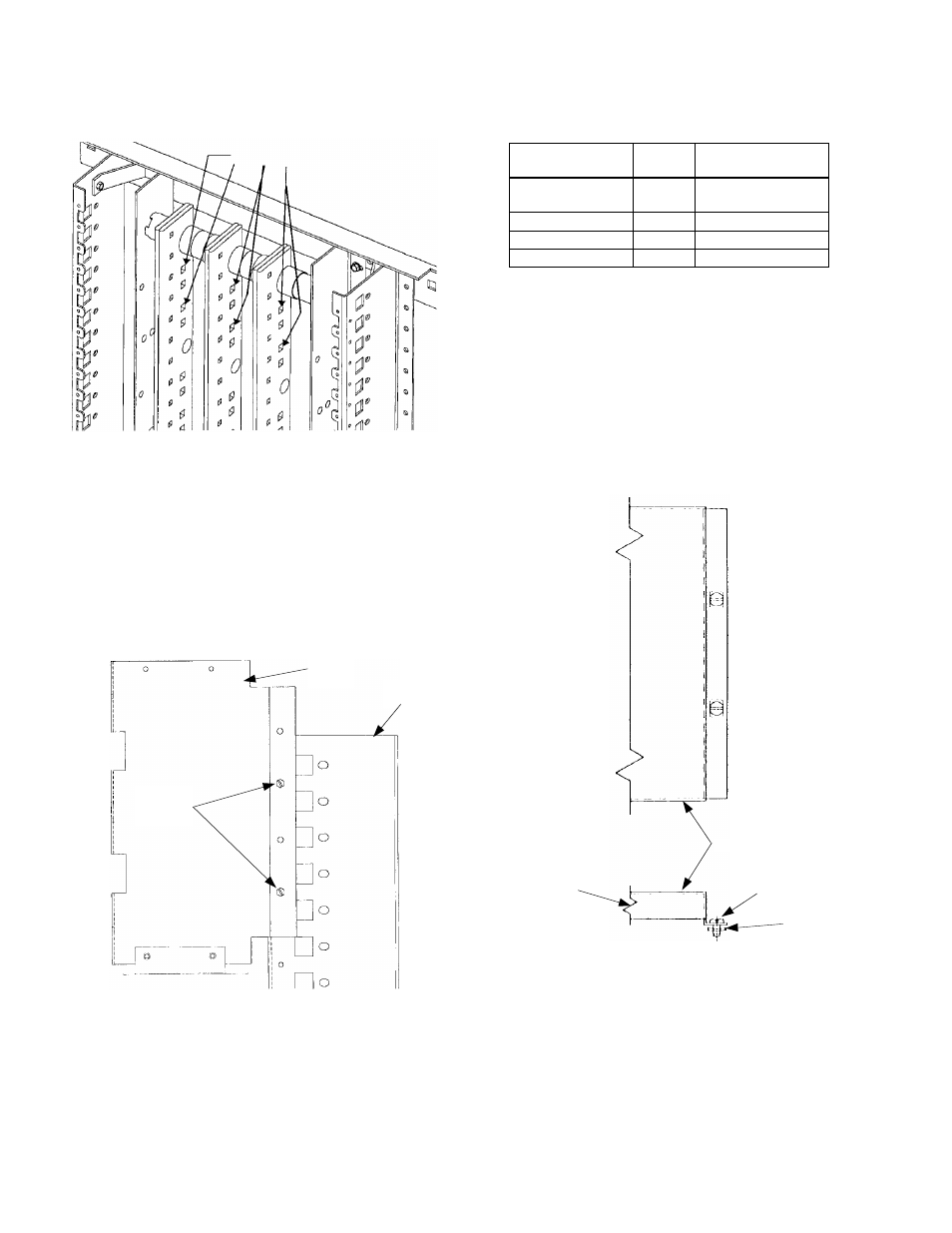
3. Align the mounting holes.
Align the lug strap
mounting holes with the first and third bus holes from
the box end stamped
LINE
on the rear row of holes, as
shown in Figure 4.
Figure 4. Bus bar mounting holes.
4. Fasten the lug straps to the bus
using a carriage bolt,
flat washer, Belleville washer, and nut, as shown in
Figures 2 and 3. Tighten these bolted connections to
200–250 in.-lb.
5. Install the wire barriers.
Position the wire barriers so
that the second and fourth holes from the top of the
wire barrier align with the first and fourth holes of the
panel side rails or Z rails, as shown in Figure 5. Secure
the wire barriers to the panel side rails or Z rails using
the thread-forming screws supplied.
Figure 5. Wire barrier installation.
6. Wire the lugs
using the conductor sizes and tightening
torques listed in Table 1. If compression lugs are used,
follow the tool and wire information stamped on the
lugs.
Lug Part No.
Torque,
in.-lb.
Wire Size
(# of wires)
252B3638G9–10
375
8–500 kcmil (1)
#2/0–600 kcmil (1)
252B3638G1–2
450
2/0–600 kcmil (4)
252B3638G3–8
450
2/0–600 kcmil (8)
GEA2-750
475
3/0–750 kcmil (2)
Table 1. Recommended tightening torque and wire sizes.
7. Install the cover.
Lug kits whose catalog numbers have
an F suffix include cover plates. Two covers are
included: one for 36"- and 40"-wide boxes and one for
44"-wide boxes. Choose the appropriate cover for the
box to be used.
Attach the cover to the barriers in four places with the
screws and nut fasteners provided, as shown in Figures
6 and 7. Also use the black spacers for the style of
cover shown in Figure 7. Tighten the screws to 25–30
in.-lb.
Figure 6. Installing the cover.
Mounting Holes
Wire
Barrier
Panel Side
Rail
Thread-
Forming
Screws
Cover
Screw
Nut
Fastener
Barrier