GE Industrial Solutions Spectra Series Power Panelboards AMB Main Lug Kit User Manual
Spectra series™ power panelboards, Application, Installation
g
Spectra Series™ Power Panelboards
Type AMB Main Lug Kit
Application
These instructions apply to main lug kits with the
following catalog numbers:
AMB2600MA
AMB3600MA
AMB2600MC
AMB3600MC
AMB2120MA
AMB3120MA
AMB2120MA
AMB3120MC
AMB2120DMC
AMB3120DMC
AMB2120DMA
AMB3120DMA
Installation
WARNING:
Danger of electrical shock or injury.
Turn
OFF power ahead of the panelboard or
switchboard before working inside the
equipment or removing any component
.
Equipment is to be installed and maintained by
properly trained and qualified personnel only.
1. Orient the lug base
with the lug wire holes facing the
end of the box marked
LINE.
For catalog numbers
A M B 2 1 2 0 M A ,
A M B 3 1 2 0 M A ,
A M B 2 1 2 0 M C ,
AMB3120MC, AMB2120DMC, AMB3120DMC,
AMB2120DMA, and AMB3120DMA, feed the lug
tangs through the support, as shown in Figure 1.
Catalog numbers AMB2600MA, AMB3600MA,
AMB2600MC, and AMB3600MC do not contain this
support.
CAUTION:
Failure to properly insert the lug
tang in the support for the required kits will
cause destructive behavior during short-circuit
conditions.
Figure 1. Lug tang inserted into the support.
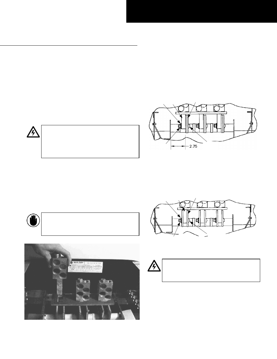
2. Locate the mounting position.
For Spectra APNB bolt-
on style interiors, locate the side of the panelboard
interior in which the dimension from the nearest bus
face to the inner face of the bus support rail is 2.75
inches, as shown in Figure 2. Lug tangs will be
mounted on this side of each phase of the bus.
Figure 2. Lug tang position relative to the bus bars of a Spectra
APNB bolt-on interior.
For Spectra APN plug-in style interiors, the lug tangs
are positioned between the buses for each phase, as
shown in Figure 3. For Spectra APN interiors, rated at
600 A or less, the lug tangs are positioned as described
above for Spectra APNB interiors.
Figure 3. Lug tang position relative to the bus bars of a Spectra APN
plug-in interior.
WARNING:
Positioning the lugs correctly
relative to the bus bars is crucial to product
safety and if installed improperly will result in
electrical shock or injury.
3. Align the mounting holes.
Align the lug tang
mounting holes with the first and second bus holes
from the box end stamped
LINE
on the rear row of
holes, as shown in Figure 4.
DEH070 Installation Instructions
R02
Lug
Tang
Bus
Carriage
Bolt
Conical
Washer
Nut
Lug
Tang
Bus
Carriage
Bolt
Conical
Washer
Nut