Ge energy, Car1612fp series rectifier, Status and control – GE Industrial Solutions CAR1612FP series User Manual
Page 4: Signal definitions, Input signals, Output signals
GE Energy
CAR1612FP series rectifier
Input: 85Vac to 264Vac; Output: 12 Vdc @ 1600W; 3.3Vdc or 5 Vdc @ 1A
November 1, 2012
©2012 General Electric Company. All rights reserved.
Page 4
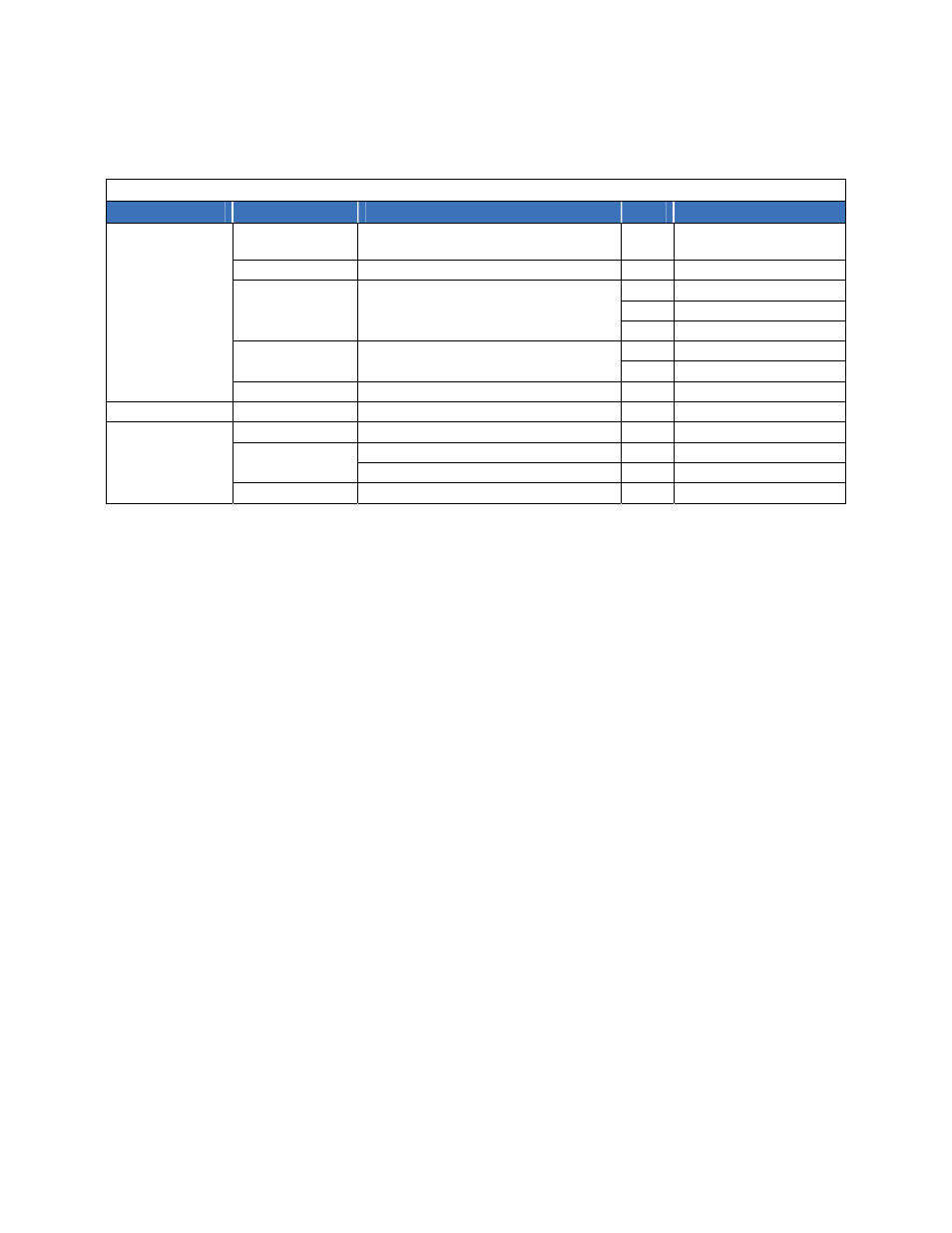
EMC
Parameter
Criteria
Standard
Level
Test
AC input
Conducted emissions
EN55022, FCC Docket 20780 part 15, subpart J
EN61000-3-2
A* 0.15
–
30MHz
0 – 2 KHz
Radiated
emissions**
EN55022 A*
30
–
10000MHz
Voltage dips
EN61000-4-11
B
-30%, 10ms
B -60%,
100ms
B -100%,
5sec
Voltage surge
EN61000-4-5
A
4kV, 1.2/50µs, common mode
A
2kV, 1.2/50µs, differential mode
immunity
Fast transients
EN61000-4-4
B
5/50ns, 2kV (common mode)
Enclosure immunity
Conducted RF fields
EN61000-4-6
A
130dBµV, 0.15-80MHz, 80% AM
Radiated RF fields
EN61000-4-3
A
10V/m, 80-1000MHz, 80% AM
ENV
50140
A
ESD
EN61000-4-2
B
4kV contact, 8kV air
*
Note: Contact the factory for a recommended external EMI filter to meet Class B emissions
**
Radiated emissions compliance is contingent upon the final system configuration.
Status and Control
Details of analog controls are provided in this data sheet
under Signal Definitions. GE Energy will provide separate
application notes on the I2C protocol. Contact your local
GE Energy representative for details.
Signal Definitions
All signals and outputs are referenced to Output return.
These include ‘Vstb return’ and ‘Signal return’.
Input Signals
Voltage programming (V
prog
):
An analog voltage on this
signal can vary the output voltage ± 10% from 10.8Vdc to
13.2Vdc. The equation of this signal is:
V
out
= 10.8 + (V
prog
* 0.96) 0 < V
prog
< 2.5
If 2.5 < Vprog < 3, the output is 13.2V. If Vprog is > 3V
or left open the programming signal is ignored and the
unit output is set at the setpoint of 12Vdc.
Load share (Ishare):
This is a single wire analog signal
that is generated and acted upon automatically by power
supplies connected in parallel. The Ishare pins should be
tied together for power supplies if active current share
among the power supplies is desired. No resistors or
capacitors should get connected to this pin.
Remote ON/OFF:
Controls the presence of the main
12Vdc output voltage. This is an open collector, TTL level
control signal. This signal needs to be pulled HI
externally through a resistor. Maximum collector voltage
is 12Vdc and the maximum sink current is 4mA. A Logic
1 (TTL HI level) turns ON the 12Vdc output, while a Logic
0 (TTL LO level) turns OFF the 12Vdc output.
A turn OFF command either through this signal (Remote
ON/OFF) or firmware commanded would turn OFF the
12V output.
Enable:
This is a short signal pin that controls the
presence of the 12Vdc main output. This pin should be
connected to ‘output return’ on the system side of the
output connector. The purpose of this pin is to ensure
that the output turns ON after engagement of the power
blades and turns OFF prior to disengagement of the
power blades.
Write protect (WP):
This signal protects the contents of
the EEPROM from accidental over writing. When left
open the EEPROM is write protected. A LO (TTL
compatible) permits writing to the EEPROM. This signal
is pulled HI internally by the power supply.
Output signals
Output current monitor (Imon):
A voltage level
proportional to the delivered output current is present on
this pin. 134A = 3V, 100A = 2.25V; accuracy: ± 10%.
AC OK:
A TTL compatible status signal representing
whether the input voltage is within the anticipated range.
This signal needs to be pulled HI externally through a
resistor. Maximum sink current ≤ 4mA and the max
voltage is 12Vdc. Open collector (HI) on this signal
indicates that the input voltage is applied within the
specified input range.
DC OK:
A TTL compatible status signal representing
whether the output voltage is present. This signal needs