GE Industrial Solutions EntelliGuard G NETWORK INTERLOCK DEVICE User Manual
Page 2
4. Network interlock uses two locations of
the coils on the mechanism top plate at 1
st
& 2
nd
locations as shown in Fig. 2
5. Tilt the NI forward and engage the front
hooks into the mechanism top support
plate as shown in the Fig. 4
Figure 6
8. Connect the NI status switch wire
assembly plugs to the B4-B5-B6 locations
on the block B
9. Ensure that the plug in connection is firm
and that the plug is inserted into the
correct terminals.
10. To reinstall the cover, rotate the charging
handle down and slide the front cover
over the handle to assemble the front
cover to housing as shown in Fig. 7
Figure 4
6. Tilt the device backwards until the rear
hooks engage in the slots on the
mechanism top support plate as shown in
the Fig. 5
11. Ensure the fascia is aligned properly with
the trip unit and the pad lock features of
the breaker.
12. Fasten the 6 mounting screws of fascia
with the housing using a pozidrive
screwdriver. Apply torque of 6 Nm (4.42 ft-
lbs)
Figure 5
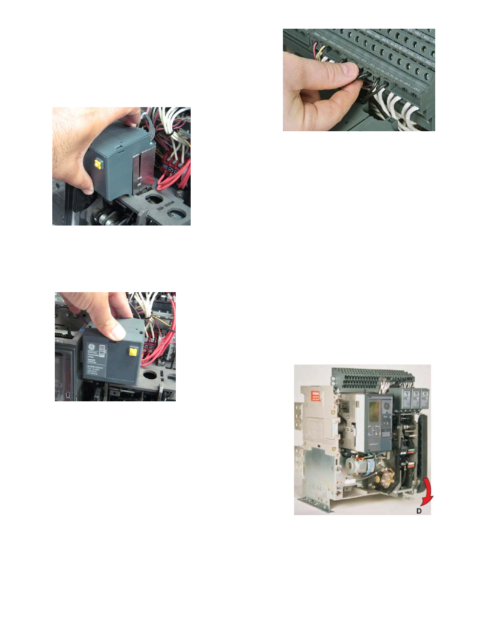
7. Connect the input wire assembly plugs to
the A5-A6 and A7-A8 locations marked on
the secondary disconnect block A as
shown in Fig. D.
Figure 7
2