Procedure for aluminum terminations, For two-pole devices on three-phase systems only – GE Industrial Solutions Spectra Series Power Panelboards 30–200 Ampere Fusible Switch User Manual
Page 2
4. Wire the circuits.
Refer to the label inside for the
switch cover for the proper tightening torques.
5. Filler plates.
Install filler plates in all unused spaces
from the filler kits included with the switch. Order
replacement filler plates from the list in Table 1.
Current,
A
Voltage
Fuse
Type
Switch Encl.
Width, in.
Filler Kit
Cat. No.
30
240/600 H, J, K, R
26
AFP4X
240
H, K, R
AFP4X
60
600
H, J, K, R
26
AFP5X
H, J, K, R
AFP5X
100
240/600
T
26
AFP7T
T, J
26
AFP7T
H, J, K, R
26
AFP7X
200
240/600
H, K, R
32
AFP7X2
Table 1. Replacement filler plate kits.
Procedure for Aluminum Terminations
1.
Strip the insulation, being careful to not nick the wire.
2.
Clean the wire strands with a wire brush.
3.
Thoroughly coat the stripped conductor with a
suitable antioxidant compound, such as ALNOX or
PENETROX A13.
4.
Insert the conductor and tighten the connector screw
to the torque indicated on the rating label.
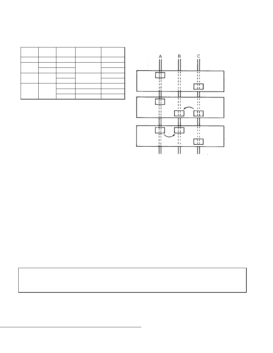
For Two-Pole Devices on Three-Phase
Systems Only
To balance the panelboard load, remove the screws on the
appropriate bus clip, reposition the bus clip as shown in
Figure 8, then reinstall and tighten the screws to 27–32 in-
lb.
Figure 4. Repositioning the bus clip to balance the load.
g
GE Industrial Systems
General Electric Company
41 Woodford Ave., Plainville, CT 06062
GEH5548 R02 0901
© 2001 General Electric Company
These instructions do not cover all details or variations in equipment nor do they provide for every possible contingency that
may be met in connection with installation, operation, or maintenance. Should further information be desired or should
particular problems arise that are not covered sufficiently for the purchaser’s purposes, the matter should be referred to the
GE Company.
A & C Phase
As Received
A & B Phase
B & C Phase