Getting started, 1 panel layout – SENA LS110 User Manual
Page 11
11
2: Getting Started
This chapter describes how to set up and configure the LS110.
- 2.1 Panel Layout explains the panel layout and LED indicators.
- 2.2 Connecting the Hardware describes how to connect the power, the network, and the serial
device to the LS110.
- 2.3 Accessing Console Port describes how to access the console port using a serial console at a
local site or telnet console at a remote site.
- 2.4 Command Usages described how to use command set of the LS110 to configure and view
parameter values and status.
Following items are required to get started.
- One DC power adapter (included in the package).
- One serial console cable for configuration (included in the package).
- One RS-232 serial cable for connecting the RS-232 serial device.
- One PC with Network Interface Card (hereafter, NIC) and/or one RS232 serial port.
- Terminal emulation program running on the PC
- One Ethernet cable
2.1 Panel Layout
The LS110 has five LED indicator lamps for status display. Two lamps on the upper side indicate
status of the 10 Base-T Ethernet Link and Act. Next lamp indicates status of receive and transmit of
the serial port. Next two lamps indicate the system running status and the system power-on status.
Table 2-1 describes function of each LED indicator lamp.
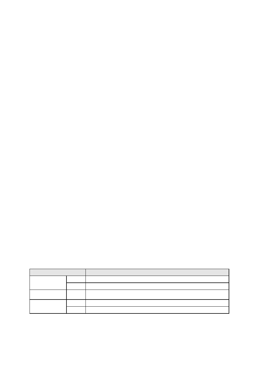
Table 2-1 LED indicator lamps
Lamps
Function
Link
Solid YELLOW, if connected to 10 Base-T Ethernet network
10 Base-T
Act
Blinks whenever there is any activity on the LS110 Ethernet port
Serial port
Rx/Tx
Blinks whenever there is any incoming or outgoing data through the serial
port of the LS110. GREEN on outgoing, RED on incoming.
Ready
Solid GREEN, if system is running and ready to be used.
Status
Power
Solid RED, if power is supplied