Ocean Optics HR2000+ Install User Manual
Page 30
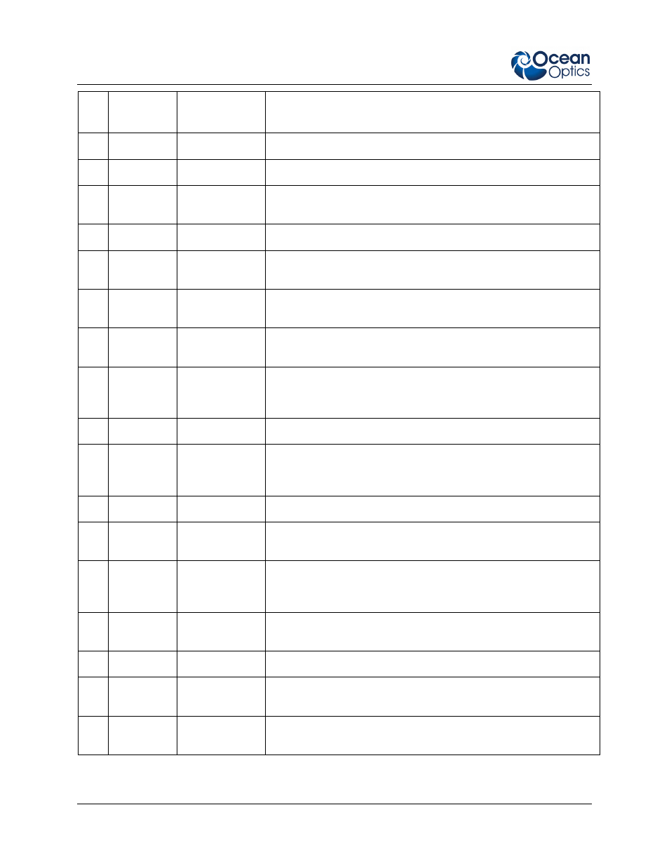
B: HR2000+ Specifications
24
294-00000-000-02-201012
Pin
#
Function
Input/Output
Description
5
Ground
Input/Output
Ground
6
I
2
C SCL
Input/Output
I
2
C clock signal for communication to other I
2
C peripherals
7
GPIO (0)
Input/Output
General purpose software-programmable, digital input/output
(channel number) Reserved
8
I
2
C SDA
Input/Output
I
2
C data signal for communication to other I
2
C peripherals
9
GPIO (1)
Input/Output
General purpose software-programmable, digital input/output
(channel number) Reserved
10
Ext.
Trigger In
Input
TTL input trigger signal – See External Triggering Options
document for information.
11
GPIO (3)
Input/Output
General purpose software-programmable, digital input/output
(channel number) Reserved
12
V
CC
, V
USB
,
or 5V
IN
Input or Output
Input power pin for HR2000+ – When operating via USB, this pin
can power other peripherals – Ensure that peripherals comply with
USB specifications
13
Reserved
Output
Reserved
14
V
CC
, V
USB
,
or 5V
IN
Input or Output
Input power pin for HR2000+ – When operating via USB, this pin
can power other peripherals – Ensure that peripherals comply with
USB specifications
15
Reserved
Input
Reserved
16
GPIO (4)
Input /Output
General purpose software-programmable, digital input/output
(channel number) Reserved
17
Single
Strobe
Output
TTL output pulse used as a strobe signal – Has a programmable
delay relative to the beginning of the spectrometer integration
period
18
GPIO (5)
Input/Output
General purpose software-programmable, digital input/output
(channel number) Reserved
19
Reserved
Output
Reserved
20
Continuous
Strobe
Output
TTL output signal used to pulse a strobe – Divided down from the
master clock signal
21
SPI Chip
Select
Output
SPI Chip/Device Select signal for communication to other SPI
peripherals