Pin accessory connector pinout, Pin accessory connector pinout diagram – Ocean Optics HR2000+ Install User Manual
Page 29
B: HR2000+ Specifications
294-00000-000-02-201012
23
30-Pin Accessory Connector Pinout
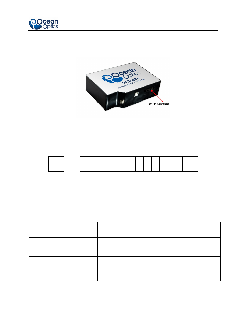
The HR2000+ features a 30-pin Accessory Connector, located on the side of the unit as shown:
Location of HR2000+ 30-Pin Accessory Connector
30-Pin Accessory Connector Pinout Diagram
When facing the 30-pin Accessory Connector on the front of the vertical wall of the HR2000+, pin
numbering is as follows:
2
4
6
8
10
12
14
16
18
20
22
24
26
28
30
USB
Port
1
3
5
7
9
11
13
15
17
19
21
23
25
27
29
30-Pin Accessory Connector Pinout Diagram
30-Pin Accessory Connector – Pin Definitions and
Descriptions
The following table contains information regarding the function of each pin in the HR2000+’s 30-Pin
Accessory Connector:
Pin
#
Function
Input/Output
Description
1
RS232 Rx
Input
RS232 receive signal – Communicates with a PC over DB9 Pin 3
2
RS232 Tx
Output
RS232 transmit signal – Communicates with a PC over DB9 Pin 2
3
GPIO (2)
Input/Output
General purpose software-programmable, digital input/output
(channel number) Reserved
4
V5_SW
Output
Regulated 5 Volt power pin – Supplies 50 mA (maximum)