Teccor, Brand thyristors, 8 amp sensitive & standard scrs – Littelfuse Sxx08x Series User Manual
Page 6
260
Revised: 09/23/13
©2013 Littelfuse, Inc
Specifications are subject to change without notice.
Teccor
®
brand Thyristors
8 Amp Sensitive & Standard SCRs
Sxx08xSx & Sxx08x Series
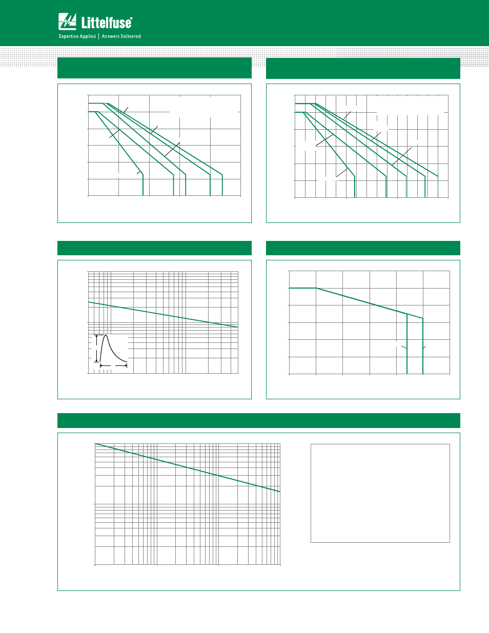
Figure 9: Maximum Allowable Ambient Temperature
vs. RMS On-State Current
0
20
40
60
80
100
120
Sxx08R
Sxx08L
Sxx08V
Sxx08RSy
Sxx08LSy
0.0 0.5 1.0 1.5 2.0 2.5
RMS On-State Current [I
T(RMS)
] - Amps
Maximum Allo
w
able Ambient
Temper
at
ur
e
(T
A
) - °C
CURRENT WAVEFORM: Sinusoidal
LOAD: Resistive or Inductive
CONDUCTION ANGLE: 180°
FREE AIR RATING
Sxx08VSy
Figure 10: Maximum Allowable Ambient Temperature
vs. Average On-State Current
0
20
40
60
80
100
120
5
.
1
0
.
1
5
.
0
0
.
0
Sxx08V
Sxx08R
Sxx08VSy
Average On-State Current [I
T(AVE)
] - Amps
Maximum Allo
w
able Ambient
Temper
at
ur
e
(T
A
) - °C
CURRENT WAVEFORM: Sinusoidal
LOAD: Resistive or Inductive
CONDUCTION ANGLE: 180°
FREE AIR RATING
Sxx08RSy
Sxx08LSy
Sxx08L
Note: xx = voltage, y = sensitivity
1
10
100
0
0
0
1
0
0
1
0
1
1
Surge Current Duration -- Full Cycles
Peak Surge (Non-repetitive)On-state
Current (I
TSM
) – Amps
Figure 13: Surge Peak On-State Current vs. Number of Cycles
SUPPLY FREQUENCY: 60 Hz Sinusoidal
LOAD: Resistive
RMS On-State Current: [I
T(RMS)
]: Maximum Rated
Value at Specified Case Temperature
Notes:
1. Gate control may be lost during and immediately
following surge current interval.
2. Overload may not be repeated until junction
temperature has returned to steady-state
rated value.
Figure 11: Peak Capacitor Discharge Current
Figure 12: Peak Capacitor Discharge Current Derating
0.0
0.2
0.4
0.6
0.8
1.0
1.2
Nor
maliz
ed P
eak Cur
rent
Sensitive SCR
0 25 50 75 100 125 150
Case Temperature (T
C
) - °C
Standard SCR
10
100
1000
0
.
0
5
0
.
10
5
.
0
Pulse Current Duration (t
w
) - ms
P
e
ak Disc
har
g
e
Cu
rr
ent (I
TM
) -
Amps
I
TRM
t
W
1.0