Teccor, Brand thyristors, Figure 6: diac v – Littelfuse Q6012LTH1LED Series User Manual
Page 4: Change vs. junction temperature, Figure 7: test circuit, Figure 8: test circuit waveform
186
Revised: 09/23/13
©2013 Littelfuse, Inc
Specifications are subject to change without notice.
Teccor
®
brand Thyristors
12 Amp Alternistor Quadrac for LED dimmer applications
Q6012LTH1LED Series
-8%
-6%
-4%
-2%
0%
2%
4%
6%
-40
-20
0
20
40
60
80
100
120
140
Junction Temperature (T
J
) -- °C
V
BO
C
h
a
nge
-
- %
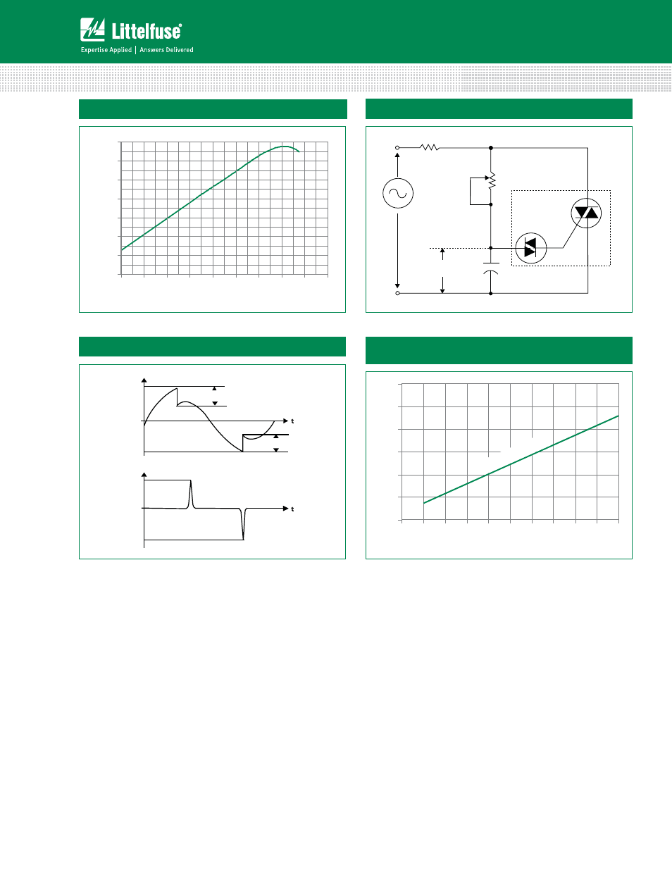
Figure 6: DIAC V
BO
Change vs. Junction Temperature
D.U.T.
MT2
MT1
C
T
= 0.1
μF
T
V
C
120 V
60 Hz
R
L
Figure 7: Test Circuit
ΔV+
ΔV-
V
C
+V
BO
-V
BO
0
I
L
+I
PK
-I
PK
0
t
t
Typical pulse base width is 10μs
Figure 8: Test Circuit Waveform
0
50
100
150
200
250
300
0.1
0.2
0.3
0.4
0.5
0.6
0.7
0.8
0.9
1.0
Triggering Capacitance (C
T
) – μF
Peak Output Current (I
PK
) – mA
Typical (3
5V Device)
Figure 9: Peak Output Current vs Triggering Capacitance
(Per Figure 7)
See also other documents in the category Littelfuse Hardware:
- SP1008 Series (4 pages)
- PGR-6130 Series (1 page)
- L600 PCB Series (1 page)
- Sxx12x Series (9 pages)
- PGR-6800 Series (1 page)
- FH2 80V Series (1 page)
- SP3006 Series (4 pages)
- Stud Assembly Module (4-stud) (1 page)
- 595 Series (1 page)
- CablePro Series (1 page)
- SE-325 Series (1 page)
- SP4020 Series (4 pages)
- CBO Series (1 page)
- M1500 Series (2 pages)
- Fixed Voltage TwinSLIC Series DO-214 (4 pages)
- Q2L Series 3.3x3.3 QFN (4 pages)
- Asymmetrical Multiport Series MS-013 (4 pages)
- iTMOV Varistor Series (8 pages)
- TCMOV Varistor Series (6 pages)
- FUN Series (1 page)
- MG12300D-BN2MM Series (5 pages)
- TOE Series (2 pages)
- SMA6J Series (5 pages)
- E5200 Series (1 page)
- SL0902A Series (5 pages)
- PGN Series (1 page)
- FBMOV Varistor Series (3 pages)
- T3500 Series (2 pages)
- 3.0SMC Series (5 pages)
- TPSMA6L Series (6 pages)
- P0080T023G5 (6 pages)
- SP1004 Series (4 pages)
- Asymmetrical Discrete Series DO-214 (4 pages)
- PLEDxSW Series (5 pages)
- 438 Series (3 pages)
- M2500 Series (1 page)
- SD05 Series (4 pages)
- 1210L Series (6 pages)
- ZA Varistor Series (14 pages)
- HQ6025xH5 Series (8 pages)
- Battrax Series DO-214 (4 pages)
- MLA Varistor Series (8 pages)
- LA120X Series (1 page)
- TPSMB Series (6 pages)
- 434 Series (3 pages)