Teccor, Brand thyristors – Littelfuse Q6012LTH1LED Series User Manual
Page 2
184
Revised: 09/23/13
©2013 Littelfuse, Inc
Specifications are subject to change without notice.
Teccor
®
brand Thyristors
12 Amp Alternistor Quadrac for LED dimmer applications
Q6012LTH1LED Series
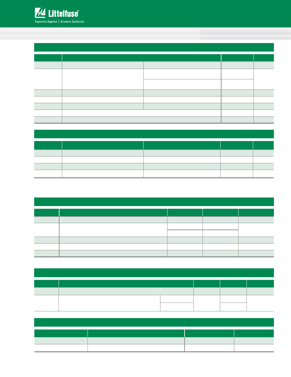
Absolute Maximum Ratings
Symbol
Parameter
Value
Unit
I
T(RMS)
RMS forward current
Tc = 90°C
12
A
I
TSM
Peak non-repetitive surge current
single half cycle; f = 50Hz;
T
J
(initial) = 25°C
110
A
single half cycle; f = 60Hz;
T
J
(initial) = 25°C
120
I
2
t
I
2
t value for fusing
t
p
= 8.3ms
60
A
2
s
di/dt
Critical rate-of-rise of on-state current
f = 60Hz; T
J
=110°C
70
A/μs
I
GM
Peak gate current
T
J
= 110°C
1.5
A
T
stg
Storage temperature range
-40 to 150
°C
T
J
Operating junction temperature range
-40 to 110
°C
Electrical Characteristics
(T
J
= 25°C, unless otherwise specified)
– Alternistor Quadrac
Symbol
Test Conditions
Value
Unit
I
H
I
T
= 20mA (initial)
MAX.
8
mA
dv/dt
V
D
= V
DRM
; gate open; T
J
=110°C
MIN.
45
V/μs
dv/dt(c)
di/dt(c) = 0.54 x I
T(rms)
/ ms; T
J
= 110°C
MIN.
2
V/μs
t
gt
(note 1)
TYP.
3
μs
(1) Reference test circuit in figure 7 and waveform in figure 8; C
T
= 0.1μF with 0.1μs rise time.
Trigger DIAC Specifications
Symbol
Test Conditions
Value
Unit
ΔV
BO
Breakover Voltage Symmetry
MAX.
3
V
V
BO
Breakover Voltage, forward and reverse
MIN.
33
V
MAX.
43
[ΔV±]
Dynamic Breakback Voltage, forward and reverse (note 1)
MIN.
5
V
I
BO
Peak Breakover Current
MAX.
25
uA
C
T
Trigger Firing Capacitance
MAX.
0.1
μF
(1) Reference test circuit in figure 7 and waveform in figure 8.
Static Characteristics
Symbol
Test Conditions
Value
Unit
V
TM
I
T
= 1.41 x I
T(rms)
A; t
p
= 380μs
MAX.
1.6
V
I
DRM
/ I
RRM
V
DRM
/ V
RRM
T
J
= 25°C
MAX.
10
μA
T
J
= 110°C
1000
Thermal Resistances
Symbol
Parameter
Value
Unit
R
T(J-C)
Junction to case (AC)
2.3
°C/W
R
T(J-A)
Junction to ambient
50
°C/W