Teccor, Brand thyristors – Littelfuse Q6012LTH1LED Series User Manual
Page 3
185
Revised: 09/23/13
©2013 Littelfuse, Inc
Specifications are subject to change without notice.
Teccor
®
brand Thyristors
12 Amp Alternistor Quadrac for LED dimmer applications
Q6012LTH1LED Series
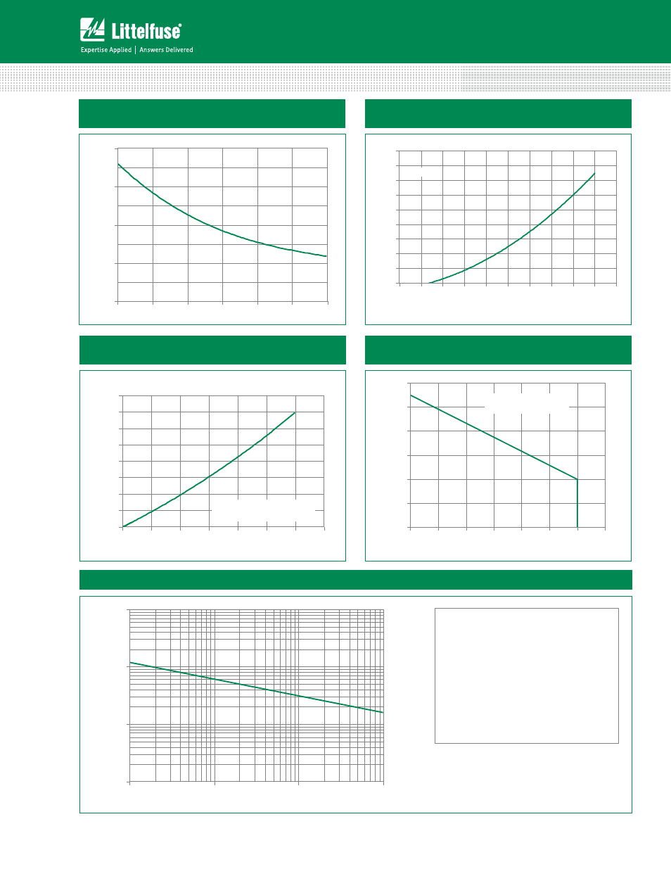
Figure 1: Normalized DC Holding Current
vs. Junction Temperature
Junction Temperature (T
J
) -- °C
Ratio of I
H
/I
H
(T
J
= 2
5
°C)
0.0
0.5
1.0
1.5
2.0
-40
-15
10
35
60
85
110
T
J
= 25°C
0
5
10
15
20
25
30
35
40
45
0.7
0.8
0.9
1.0
1.1
1.2
1.3
1.4
1.5
1.6
1.7
Instantaneous On-state Voltage (v
T
) – Volts
Instantaneous On-state Current (i
T
) – Amps
0
2
4
6
8
10
12
14
16
0
2
4
6
8
10
12
14
RMS On-State Current [I
T(RMS)
] - (Amps)
Av
e
ra
g
e
O
n
-S
tate
P
o
wer D
is
si
p
a
ti
o
n
[P
D(
AV
)
] - (Watts
)
CURRENT WAVEFORM: Sinusoidal
LOAD: Resistive or Inductive
CONDUCTION ANGLE: 360°
70
80
90
100
110
120
130
0
2
4
6
8
10
12
14
RMS On-State Current [I
T(RMS)
] - Amps
M
axi
m
u
m
A
ll
o
w
a
b
le C
ase T
e
m
p
er
at
u
re
(T
C
) - °
C
CURRENT WAVEFORM: Sinusoidal
LOAD: Resistive or Inductive
CONDUCTION ANGLE: 180°
Figure 2: On-State Current vs. On-State Voltage
(Typical)
Figure 3: Power Dissipation vs. RMS On-State Current
(Typical)
Figure 4: Maximum Allowable Case Temperature
vs. RMS On-State Current
Figure 5: Surge Peak On-State Current vs. Number of Cycles
1
10
100
1000
1
10
100
1000
Surge Current Duration -- Full Cycles
Peak Surge (Non-repetitive)
On-state Current (I
TSM
) – Amps
Supply Frequency: 60Hz Sinusoidal
Load: Resistive
RMS On-State Current: [I
T(RMS)
]: Maximum Rated
Value at Specific Case Temperature
Notes:
1. Gate control may be lost during and immediately
following surge current interval.
2. Overload may not be repeated until junction
temperature has returned to steady-state
rated value.