Transient voltage suppression diodes, Tvs diode arrays, Surface mount – 3000w > smdj-hr series – Littelfuse SMDJ-HR Series User Manual
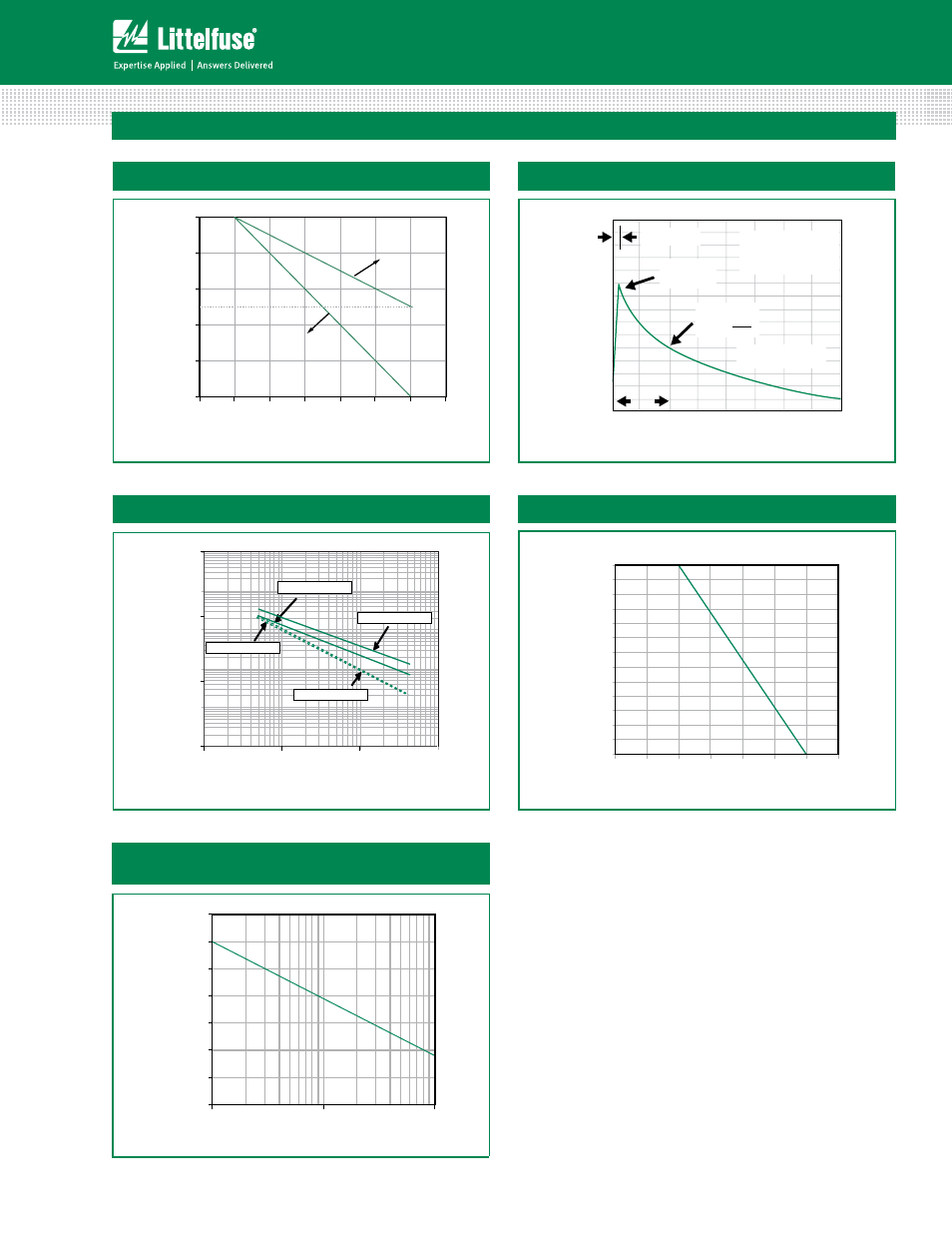
Page 4: Family of products), Ratings and characteristic curves, Continued), Figure 3 - peak pulse power
Transient Voltage Suppression Diodes
58
TVS Diode Arrays
(SPA
™
Family of Products)
©2013 Littelfuse, Inc.
Specifications are subject to change without notice.
Revised: 11/18/13
Surface Mount – 3000W > SMDJ-HR series
SMDJ-HR Series
Ratings and Characteristic Curves
(T
A
=25°C unless otherwise noted)
(Continued)
I
PPM
- P
eak P
ulse Cur
rent, %
I
RSM
0
0
50
100
150
1.0
2.0
3.0
4.0
tr=10µsec
Peak Value
IPPM
IPPM
2
TJ=25°C
Pulse Width(td) is defined
as the point where the peak
current decays to 50% of IPPM
10/1000µsec. Waveform
as defined by R.E.A
td
t-Time (ms)
Half Value
IPPM
( )
1
10
100
1000
10000
100000
1.0
10.0
100.0
1000.0
Cj
(p
F)
V
BR
- Reverse Breakdown Voltage (V)
Bi-directional V= OV
Uni-directional @ VR
Bi-directional @ VR
Uni-directional V= OV
0
0.5
1
1.5
2
2.5
3
3.5
4
4.5
5
5.5
6
6.5
0
25
50
75
100
125
150
175
P
M(
AV
)
, St
ead
y
Sa
te
Po
wer
Di
ssi
pa
tion
(W
)
T
A
- Ambient Temperature(ºC)
Figure 4 - Pulse Waveform
Figure 5 - Typical Junction Capacitance
Figure 6 - Steady State Power Derating Curve
1
10
100
Number of Cycles at 60 Hz
0
50
100
150
200
250
300
350
I
FSM
- Peak Forward Surge Current
(A)
Figure 7 - Maximum Non-Repetitive Peak Forward
Surge Current Uni-Directional only
0
20
40
60
80
100
0
25
50
75
100
125
150
175
Pe
ak
Pu
lse
Po
wer
(P
PP
) or Current
(I
PP
) Derating in Percentage
%
T
j
- initial temperature (ºC)
50
Peak Pluse Power
(Single Pluse)
Average Power
Figure 3 - Peak Pulse Power
4