GE P&W Spiral Wound Membranes - OSMO BEV UF Series User Manual
Osmo bev uf series, Beverage and bottled water production, Fact sheet
Fact Sheet
Find a contact near you by visiting www.gewater.com and clicking on “Contact Us”.
* Trademark of General Electric Company; may be registered in one or more countries.
©2013, General Electric Company. All rights reserved.
FS1279EN.doc Nov-13
OSMO BEV UF Series
Beverage and Bottled Water Production
The OSMO BEV UF membrane element is engi-
neered to provide beverage plants with consistent,
high quality water for production of carbonated soft
drinks, juices, and sport drinks. The OSMO BEV UF
element creates an absolute barrier to cryptospor-
idium and giardia, and rejects color and organics
(naturally occurring tannins, humics, fulvics, etc.)
The OSMO BEV UF element offers true multiple bar-
rier security with the lowest energy consumption. It
has a nominal MWCO of 6,000Da.
Features include a Full-Fit* design that eliminates
the stagnant zone associated with industrial fiber-
glass wrapped elements and their brine seals,
which can act as a site for bacterial growth. The
OSMO BEV UF element forms a flush-fit with the in-
ner diameter of the membrane element housing,
creating a self-cleaning effect. This design also of-
fers less pressure resistance than an industrial fi-
berglass wrapped element, resulting in lower brake
horsepower and substantial energy savings.
The OSMO BEV UF membrane is following a 100%
Wet Test Quality Assurance.
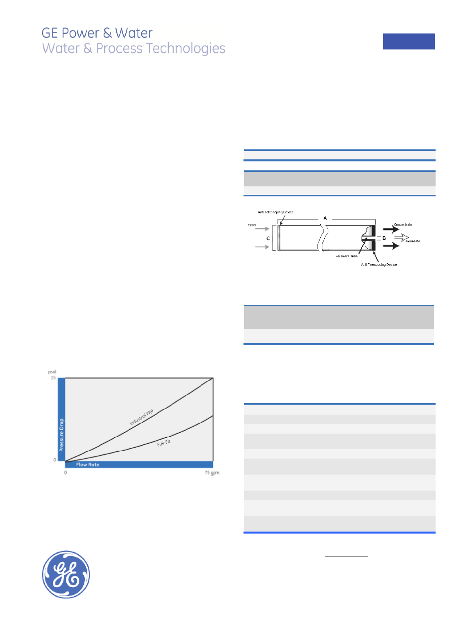
Figure1: High Flow Rate at Low Pressure Drop
Table 1: Element Specification
Membrane
Polyethersulfone
Model
Active area
ft
2
(m
2
)
Outer wrap
Part
number
OSMO-BEV-UF-FF
350 (32.5)
Full-Fit*
1233034
Figure 1: Element Dimensions Diagram - Female
Table 2: Dimensions and Weight
Model
1
Dimensions, inches (cm)
Boxed
A
B
2
C
3
Weight
lbs (kg)
OSMO-BEV-UF-FF
40.0
(101.6)
1.125
(2.86)
7.9
(20.1)
32
(14.5)
1
These elements are bagged dry before shipping.
2
Internal diameter unless specified OD (outside diameter).
3
The element diameter (dimension C) is designed for optimum performance in GE
Water & Process Technologies pressure vessels. Others pressure vessel dimension
and tolerance may result in excessive bypass and loss of capacity.
Table 3: Operating and CIP parameters
Typical Operating Pressure
30-60 psi (207-414 kPa)
Typical Operating Flux
10-20GFD (15-35LMH)
Maximum Operating Pressure
450 psi (3,102 kPa)
Maximum Temperature
Continuous operation: 122°F (50°C)
Clean-In-Place (CIP): 122°F (50°C)
Minimum Crossflow
30gpm (6.8 m3/hr)
pH range
Continuous operation: 4.0-11.0,
Clean-In-Place (CIP): 2.0-11.5
Maximum Pressure Drop
Over an element: 12 psi (83 kPa)
Per housing: 50 psi (345 kPa)
Chlorine Tolerance
5,000 ppm days
Feedwater
NTU < 1
SDI < 5
Recommended Single Element
Recovery
< 15%