GE P&W Spiral Wound Membranes - HL Series User Manual
Hl series, Water softening nf elements, Fact sheet
Fact Sheet
Find a contact near you by visiting www.gewater.com and clicking on “Contact Us”.
* Trademark of General Electric Company; may be registered in one or more countries.
©2013, General Electric Company. All rights reserved.
FS1273EN.doc Nov-13
HL Series
Water Softening NF Elements
The H-Series proprietary thin-film nanofiltration
membrane elements are characterized by an ap-
proximate molecular weight cut-off of 150-300 dal-
tons for uncharged organic molecules. Divalent and
multivalent ion rejection is dependent upon feed
concentration and composition.
HL Nanofiltration Elements are used for water sof-
tening, color removal, and reduction of THM for-
mation potential.
Table 1: Element Specification
Membrane
H-Series, Thin-film membrane (TFM*)
Model
Average
permeate flow
gpd (m3/day)
1,2
Average MgSO4
rejection
1,2
Minimum MgSO4
rejection
1,2
HL2540FM
780 (3.0)
98.0%
95.0%
HL4040FM
2,400 (9.1)
98.0%
95.0%
HL8040F 365
10,800 (40.9)
98.0%
95.0%
HL8040F-400
11,500 (43.5)
98.0%
95.0%
1
Average salt rejection after 24 hours operation. Individual flow rate may vary
+25%/-15%.
2
Testing conditions: 2,000ppm MgSO4 solution at 110psi (760kPa) operating
pressure, 77°F, pH7.5 and 15% recovery.
Model
Active area
ft
2
(m
2
)
Outer wrap
Part
number
HL2540FM
27 (2.5)
Fiberglass
1207230
HL4040FM
89 (8.2)
Fiberglass
1207236
HL8040F 365
365 (33.9)
Fiberglass
1266702
HL8040F-400
400 (37.2)
Fiberglass
1207240
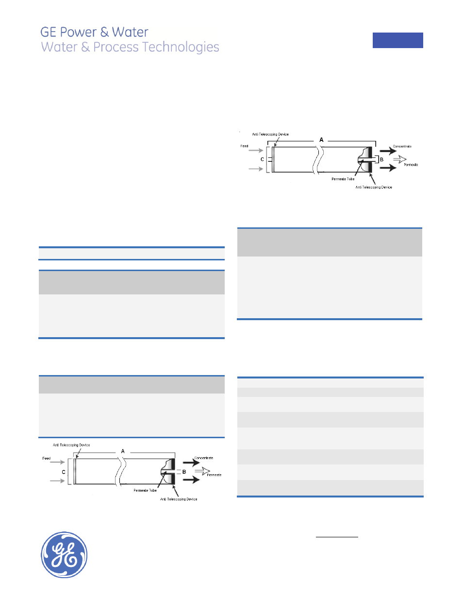
Figure 1: Element Dimensions Diagram (Female)
Figure 2: Element Dimensions Diagram (Male)
Table 2: Dimensions and Weight
Model
1
Dimensions, inches (cm)
Boxed
A
B
2
C
3
Weight
lbs (kg)
HL2540FM
40.0
(101.6)
0.75
(1.90) OD
2.4
(6.1)
5
(2.3)
HL4040FM
40.0
(101.6)
0.75
(1.90) OD
3.9
(9.9)
8
(3.5)
HL8040F 365
40.0
(101.6)
1.125
(2.86)
7.9
(20.1)
32
(14.5)
HL8040F-400
40.0
(101.6)
1.125
(2.86)
7.9
(20.1)
32
(14.5)
1
These elements are dried then bagged before shipping.
2
Internal diameter unless specified OD (outside diameter).
3
The element diameter (dimension C) is designed for optimum performance in GE
Water & Process Technologies pressure vessels. Other pressure vessel dimension
and tolerance may result in excessive bypass and loss of capacity
Table 3: Operating and CIP parameters
Typical Operating Pressure
70-300psi (483-2,069kPa)
Typical Operating Flux
10-20GFD (15-35LMH)
Maximum Operating Pressure
Tape elements: 450psi (3,103kPa)
Other outer wrap: 600psi (4,140kPa)
Maximum Temperature
Continuous operation: 122°F (50°C)
Clean In Place (CIP): 104°F (40°C)
pH Range
Optimum rejection: 6.0-7.0,
Continuous operation: 3.0-9.0,
Clean In Place (CIP): 2.0-10.5
Maximum Pressure Drop
Over an element: 12psi (83kPa)
Per housing: 50psi (345kPa)
Chlorine Tolerance
1,000+ ppm-hours,
dechlorination recommended
Feedwater
NTU < 1
SDI < 5