Material of construction, Quality assurance – GE P&W Electrodialysis Reversal (EDR) User Manual
Page 2
Page 2
FS1242EN
TOC ..................................................................... < 15 ppm (mg/l)
COD ....................................................... < 50 ppm (mg/l) as O
2
Iron .................................................................... < 0.3 ppm (mg/l)
Manganese, Aluminum ........................... < 0.1 ppm (mg/l)
H2S .................................................................... < 0.1 ppm (mg/l)
Allowable Intermittent Levels:
SDI (5 min. test) ......................................................................... 15
Turbidity ............................................................................2.0 NTU
Free Chlorine .................................................................. 30 mg/l
Material of Construction
Welded Frame................................... Painted Carbon Steel
Dilute and Concentrate Piping ...................... Sch. 80 PVC
Flanges .................................................................................... ANSI
Concentrate Pump ................... Single-stage Centrifugal
Rectifier ......................................................................... NEMA 3R
Control Panel ................................................................. NEMA 4
Quality Assurance
Certification ............................................................................... UL
Facility ................................................................. ISO 9001:2000
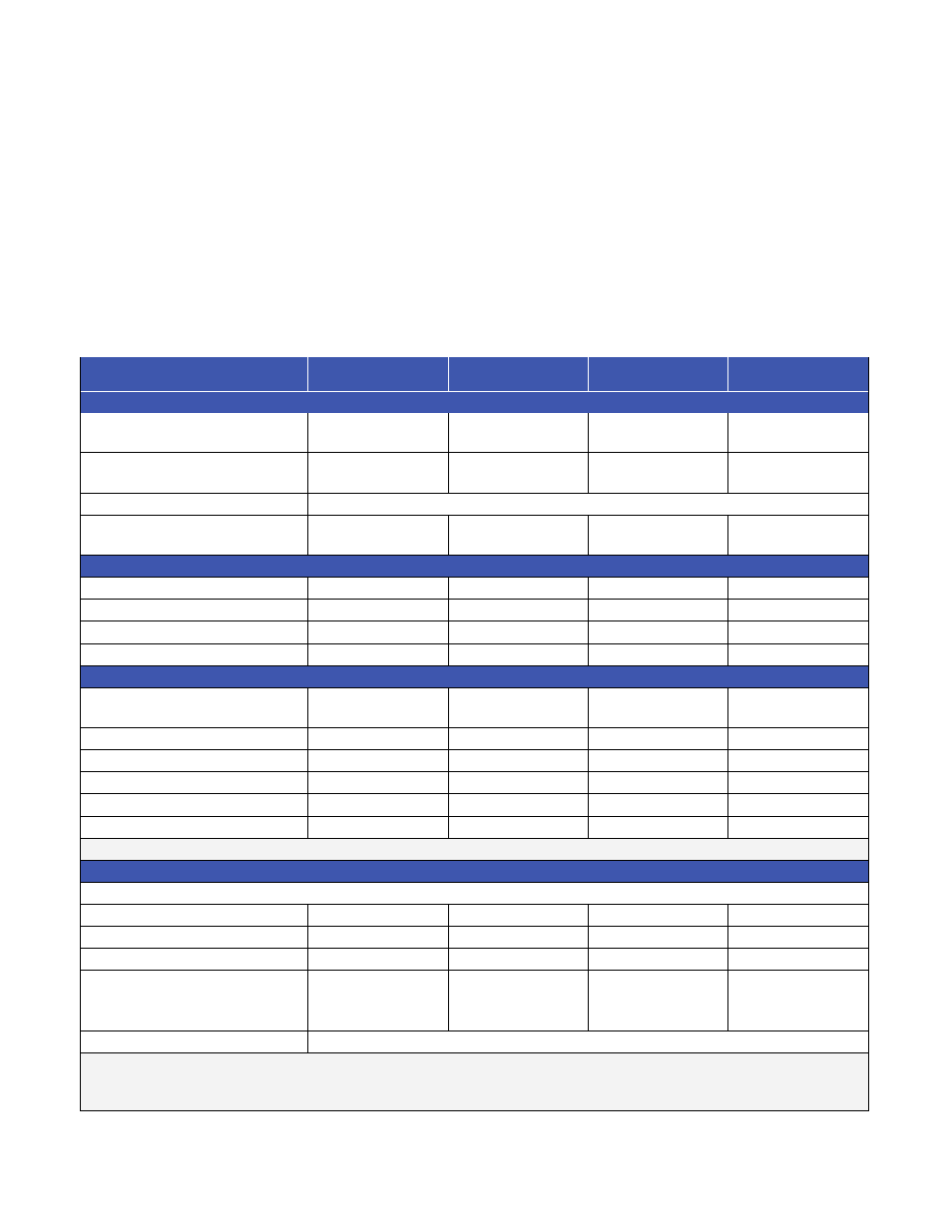
EDR 2020 2 & 4 Line Standard Systems
MODEL
2020-2L-2S
2020-2L-3S
2020-4L-2S
2020-4L-3S
Flow Rates
Product Flow Nominal
280 gpm
63.6 m
3
/h
260 gpm
59.1 m
3
/h
560 gpm
127.2 m
3
/h
520 gpm
118.2 m
3
/h
Product Flow Range
165 to 325 gpm
37.5 to 73.8 m
3
/h
165 to 270 gpm
37.5 to 61.3 m
3
/h
325 to 655 gpm
73.8 to 148.8 m
3
/h
325 to 545 gpm
73.8 to 123.8 m
3
/h
Concentrate Outlet Flow
Depends on recovery and product
Electrode Outlet Flow
2.2 gpm
8.3 lpm
2.5 gpm
9.5 lpm
4.3 gpm
16.3 lpm
5.0 gpm
19 lpm
General Information
Number of Stacks
4
6
8
12
Number of Lines
2
2
4
4
Number of Stages
2
3
2
3
Type of Stack
MK-IV-2
MK-IV-2
MK-IV-2
MK-IV-2
Dimensions
System Dimensions
Width x Length
90” x 309”
(2.3 x 7.9 m)
90” x 375”
(2.3 x 9.5 m)
169” x 493”
(4.3 x 12.5 m)
169” x 625”
(4.3 x 15.9 m)
Inlet Piping
4” (10 cm)
4” (10 cm)
6” (15 cm)
6” (15 cm)
Product Outlet Piping
4” (10 cm)
4” (10 cm)
6” (15 cm)
6” (15 cm)
Off-Spec Outlet Piping
4” (10 cm)
4” (10 cm)
6” (15 cm)
6” (15 cm)
Electrode Outlet Piping
3” (8 cm)
3” (8 cm)
3” (8 cm)
3” (8 cm)
Concentrate Outlet Piping
1.5” (4 cm)
1.5” (4 cm)
2” (5 cm)
2” (5 CM)
Note: all piping sizes are provided for nominal flow rates at 85% recovery.
Electrical
Maximum Rectifier Output (Per Stack Basis)
Stage 1
590VDC, 46A
590VDC, 26A
590VDC, 46A
590VDC, 26A
Stage 2
518VDC, 18A
518VDC, 14A
518VDC 18A
518VDC, 14A
Stage 3
420VDC, 7.5A
420VDC, 7.5A
Connection Requirement
(Includes Feed pump, which may
be supplied by others)
140 KVA
107 KVA
276 KVA
209 KVA
Typical Power consumption
2 – 4 kWh/1,000 gallons of product water
Performance, number of stages and cell pairs, recovery and power consumption are dependent on inlet feed water
quality and temperature. A Watsys projection must be completed by an authorized GE Water & Process Technologies
design representative for proper system design & for any performance guarantee to be provided.