Warning, Installation to wood stud wall (continued), Fi g. 1.3 fi g. 1.4 – Peerless-AV IM760PU-S - Installation User Manual
Page 6
6 of 12
ISSUED: 12-04-07 SHEET #: 095-9279-8 (2013-10-01)
Installation to Wood Stud Wall (continued)
• Installer must verify that the supporting surface will safely support the combined load of the equipment and all
attached hardware and components.
• Tighten wood screws so that wall plate is fi rmly attached, but do not overtighten. Overtightening can damage the
screws, greatly reducing their holding power.
• Never tighten in excess of 80 in. • lb (9 N.M.).
• Make sure that mounting screws are anchored into the center of the stud. The use of an "edge to edge" stud fi nder
is highly recommended.
• Hardware provided is for attachment of mount through max 5/8" thick drywall or plaster into 2" x 4" wood studs.
Installers are responsible to provide hardware for other types of mounting situations.
• Do not install this unit in a fi re rated wall. If you are unsure, contact your building architect or local building
department.
WARNING
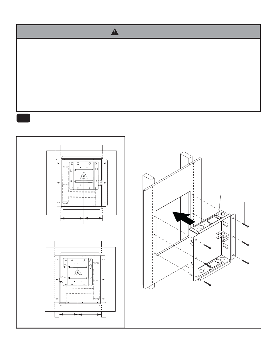
LEFT
ORIENTATION
RIGHT
ORIENTATION
fi g. 1.3
fi g. 1.4
E
B
In-wall box can be fl ipped for left of right side mount orientation as shown in fi gure 1.3. Insert in-wall box (B) into
cut-out. Level in-wall box, and mark the center of the six mounting holes. Drill six 5/32" (4mm) dia. holes 2-1/2"
(64mm) deep. Make sure in-wall box is level, secure it using six #14 x 2-1/2" wood screws (E) as shown in fi gure
1.4.
1-1
6.39"
(162mm)
8.11"
(206mm)
6.39"
(162mm)
8.11"
(206mm)