Nput, Nrush, Urrent – B&B Electronics NTPS-24-5 - Datasheet User Manual
Page 4: Urge, 24v, 5a, s
CS5.241, CS5.241-C1, CS5.241-S1
C–Series
24V, 5A, S
INGLE
P
HASE
I
NPUT
Dec. 2006 / Rev. 1.3 DS-CS5.241-EN
All parameters are specified at 24V, 5A, 230Vac, 25°C ambient and after a 5 minutes run-in time unless otherwise noted.
www.pulspower.com Phone +49 89 9278 0 Germany
4/20
6. I
NPUT
I
NRUSH
C
URRENT
S
URGE
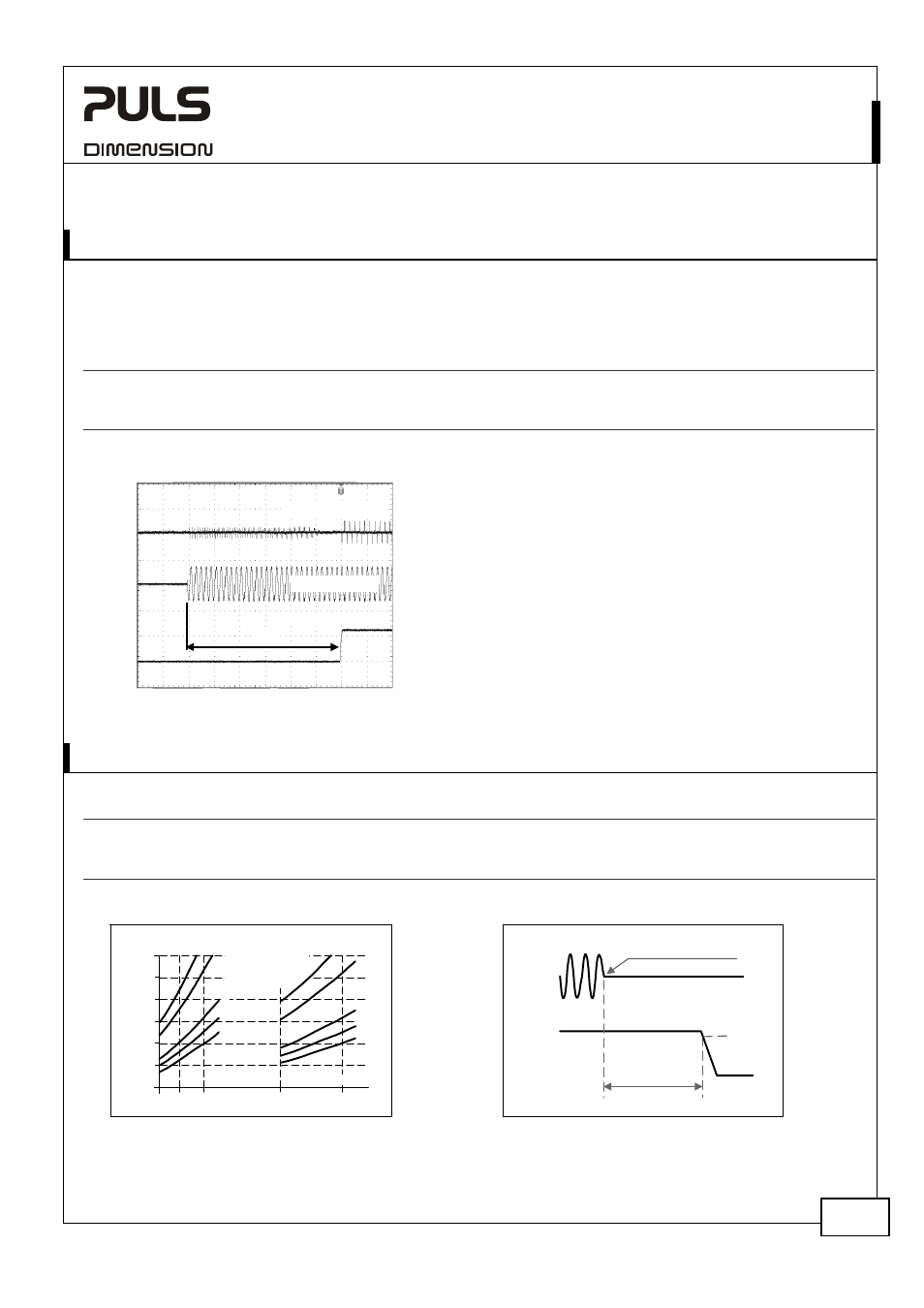
An active inrush limitation circuitry limits the input inrush current after turn-on of the input voltage.
The charging current into EMI suppression capacitors is disregarded in the first milliseconds after switch-on.
AC 100V
AC 120V
AC 230V
Inrush
current
max.
10A
peak
10A
peak
10A
peak
-25°C to +70°C
typ.
3A
peak
3A
peak
3A
peak
-25°C to +70°C
Inrush
energy
typ.
1A
2
s 1A
2
s 1A
2
s
-25°C to +70°C
Fig. 6-1 Input inrush current, typical behavior
Input Current
Input Voltage
Output Voltage
A
A:
Start-up delay = Inrush delay
Input:
230Vac
Output:
24V, 5A
Ambient: 25°C
Upper curve:
Input current 10A / DIV
Medium curve: Input voltage 500V / DIV
Lower curve:
Output voltage 20V / DIV
Time scale:
100ms / DIV
7. H
OLD
-
UP
T
IME
AC 100V
AC 120V
AC 230V
Hold-up Time
typ.
109ms
165ms
161ms
2,5A, 24V, see
Fig. 7-1
typ.
50ms 80ms 78ms
5A,
24V,
see
Fig. 7-1
typ.
37ms 62ms 63ms
6A,
24V,
see
Fig. 7-1
Fig. 7-1 Hold-up time vs. input voltage
Fig. 7-2 Shut-down behavior, definitions
0
25
50
150ms
85
120
100
180
230Vac
Hold-up Time
100
75
125
Input Voltage
a) 24V 2,5A typ.
b) 24V 2,5A min.
c) 24V 5A typ.
d) 24V 5A min.
e) 24V 6A min.
a
a
b
c
c
d
d
e
e
b
- 5%
Hold-up Time
Zero Transition
Output
Voltage
Intput
Voltage
Note: At no load, the hold-up time can be up to several seconds. The green DC-ok lamp is on during this time.