Max3420e, Usb peripheral controller with spi interface, Esd protection – Rainbow Electronics MAX3420E User Manual
Page 20
MAX3420E
whether the USB device is plugged in or not, it needs
some way to detect a plug-in event. A comparator
inside the MAX3420E checks for a valid V
BUS
connec-
tion on VBCOMP and provides a connect status bit to
the µP. Once connected, the µP can delay the logical
connection to the USB bus to perform any required ini-
tialization, and then connect by setting the CONNECT
bit to 1 in the MAX3420E register USBCTL (R15). This
connects the internal 1.5k
Ω resistor from D+ to V
CC
, to
signal the host that a device has been plugged in.
If a host turns off V
BUS
while the device is connected,
the USB rev. 2.0 specification requires that the device
must not power its 1.5k
Ω pullup resistor connected to
D+. The MAX3420E has two features to help service
this event. First, the NOVBUSIRQ bit indicates the loss
of V
BUS
. Second, the µP can set a bit called VBGATE
(V
BUS
gate) to instruct the MAX3420E to disconnect the
pullup resistor anytime V
BUS
goes away, regardless of
the CONNECT bit setting.
Crystal Selection
The MAX3420E requires a crystal with the following
specifications:
Frequency: 12MHz
± 0.25%
C
LOAD
: 18pF
C
O
: 7pf max
Drive level: 200µW
Series resonance resistance: 60
Ω max
Note: Series resonance resistance is the resistance
observed when the resonator is in the series resonant
condition. This is a parameter often stated by quartz crys-
tal vendors and is called R1. When a resonator is used in
the parallel resonant mode with an external load capaci-
tance, as is the case with the MAX3420E oscillator circuit,
the effective resistance is sometimes stated. This effec-
tive resistance at the loaded frequency of oscillation is:
R1 x ( 1 + (C
O
/ C
LOAD
))
2
For typical C
O
and C
LOAD
values, the effective resis-
tance can be greater than R1 by a factor of 2.
ESD Protection
D+, D-, and VBCOMP possess extra protection against
static electricity to protect the devices up to ±15kV. The
ESD structures withstand high ESD in all operating
modes: normal operation, suspend mode, and pow-
ered down. VBCOMP and V
CC
require 1µF ceramic
USB Peripheral Controller
with SPI Interface
20
______________________________________________________________________________________
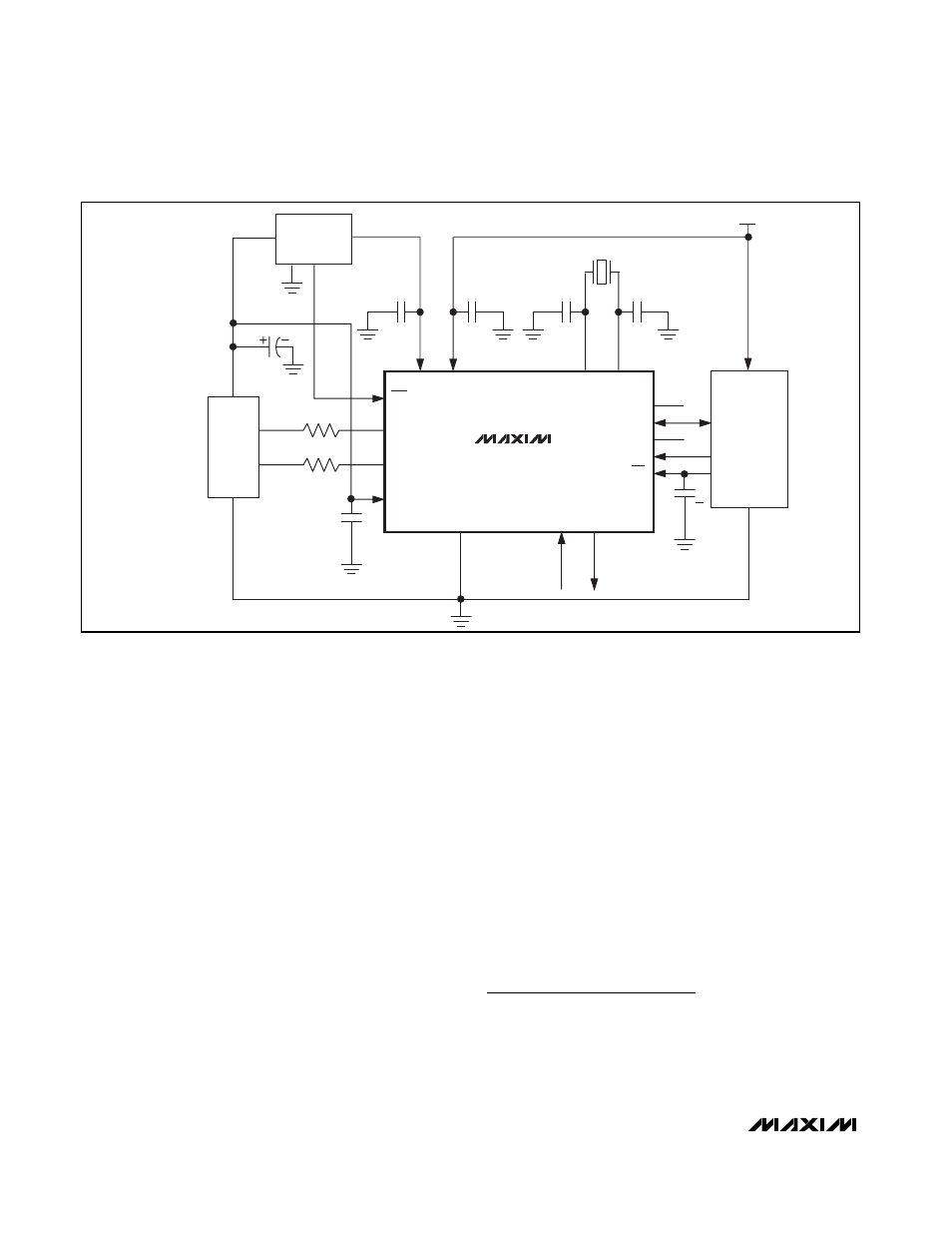
MAX3420E
V
CC
V
L
XI
XO
N.C.
N.C.
INT
MOSI
MISO
SCLK
RES
D+
D-
D+
D-
VBCOMP
SS
0.1
µF
GND
GND
GPIN GPOUT
V
BUS
33
Ω
33
Ω
1.0
µF
CERAMIC
1.0
µF
CERAMIC
C
XI
C
XO
12MHz
3.3V
REGULATOR
MAX6349TL
µP
4
4
USB
"B" CONNECTOR
C
SS
33pF*
+2.5V
4.7
µF
Figure 17. MAX3420E in a Self-Powered Application
*33pF CAPACITOR WILL NOT BE REQUIRED AFTER REDESIGN.