Rainbow Electronics MAX2063 User Manual
Page 19
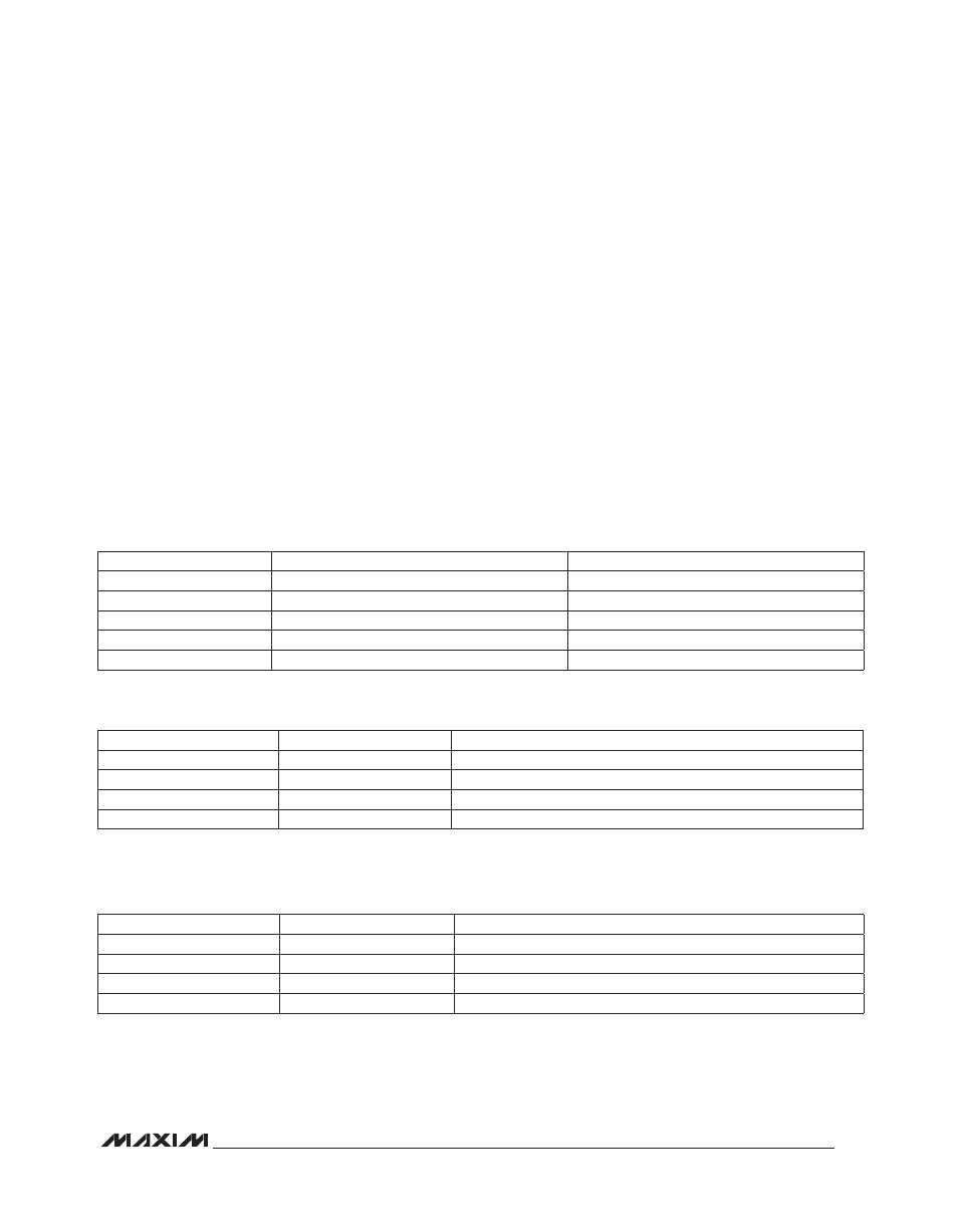
Table 4. Digital Attenuator Settings (Parallel Control, DA_SP = 0)
Table 5. Programmed Attenuation State Settings for Attenuator 1 (DA_SP = 1)
*Defined by SPI programming bits D8:D27 (see Table 3 for details).
Table 6. Programmed Attenuation State Settings for Attenuator 2 (DA_SP = 1)
*Defined by SPI programming bits D36:D55 (see Table 3 for details).
MAX2063
Dual 50MHz to 1000MHz High-Linearity,
Serial/Parallel-Controlled Digital VGA
19
If desired, the user can also program two additional
attenuation states by using the STA_B_1 control bit as a
second I/O pin. These two additional attenuation settings
are useful for software-defined radio applications where
multiple static gain settings are needed to account for
different frequencies of operation, or where multiple
dynamic attenuation settings are needed to account for
different blocker levels (as defined by multiple wireless
standards).
Power-Supply Sequencing
The sequence to be used is:
1) Power supply
2) Control lines
Layout Considerations
The pin configuration of the device is optimized to facili-
tate a very compact physical layout of the device and its
associated discrete components. The exposed pad (EP)
of the device’s 48-pin thin QFN-EP package provides a
low thermal-resistance path to the die. It is important that
the PCB on which the device is mounted be designed
to conduct heat from the EP. In addition, provide the EP
with a low inductance path to electrical ground. The EP
MUST be soldered to a ground plane on the PCB, either
directly or through an array of plated via holes.
Table 7 lists typical application circuit component values.
INPUT
LOGIC = 0 (OR GROUND)
LOGIC = 1
D0_ _
Disable 1dB attenuator
Enable 1dB attenuator
D1_ _
Disable 2dB attenuator
Enable 2dB attenuator
D2_ _
Disable 4dB attenuator
Enable 4dB attenuator
D3_ _
Disable 8dB attenuator
Enable 8dB attenuator
D4_ _
Disable 16dB attenuator
Enable 16dB attenuator
STA_A_1
STA_B_1
SETTING FOR DIGITAL ATTENUATOR 1*
0
0
Preprogrammed attenuation state 1
1
0
Preprogrammed attenuation state 2
0
1
Preprogrammed attenuation state 3
1
1
Preprogrammed attenuation state 4
STA_A_2
STA_B_2
SETTING FOR DIGITAL ATTENUATOR 2*
0
0
Preprogrammed attenuation state 1
1
0
Preprogrammed attenuation state 2
0
1
Preprogrammed attenuation state 3
1
1
Preprogrammed attenuation state 4