Detailed description, Serial interface – Rainbow Electronics MAX510 User Manual
Page 9
MAX509/MAX510
Quad, Serial 8-Bit DACs
with Rail-to-Rail Outputs
_______________________________________________________________________________________
9
• • •
• • •
• • •
• • •
A1 A0
C1 C0
D7 D6
D5 D4 D3 D2 D1 D0
MSB
LSB
DACA
DATA FROM PREVIOUS DATA INPUT
DATA FROM PREVIOUS DATA INPUT
A1 A0
C1 C0
D7
D6 D5 D4 D3 D2
D1 D0
MSB
LSB
DACD
A1
A1
A1
A1
A0
C1
C0
D7
D6 D5 D4 D3 D2 D1 D0
A1
A0
C1 C0
D7
A0
C1 C0
D7
D6 D5 D4 D3 D2 D1
D0
A1
A1
A0 C1
C0
D7
D6 D5
D4 D3 D2
D1 D0
A1
D6
D5 D4 D3 D2 D1 D0
A1
A1
DOUT
MODE 0
DOUT
MODE 1
(DEFAULT)
DIN
SCLK
• • •
CS
INSTRUCTION
EXECUTED
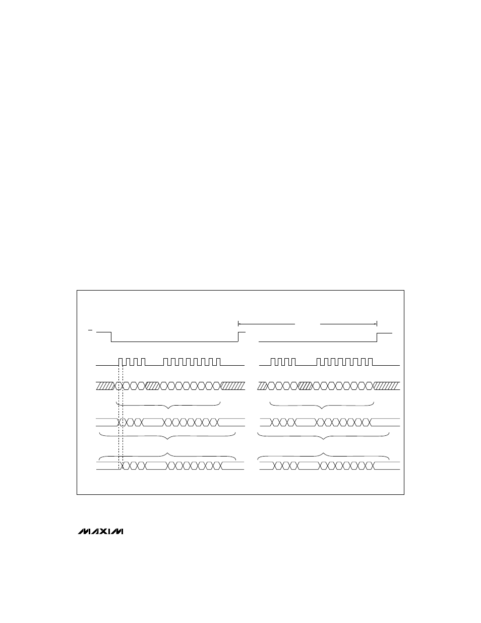
Figure 1. MAX509/MAX510 3-Wire Interface Timing
_______________Detailed Description
Serial Interface
At power-on, the serial interface and all DACs are
cleared and set to code zero. The serial data output
(DOUT) is set to transition on SCLK's rising edge.
The MAX509/MAX510 communicate with microproces-
sors through a synchronous, full-duplex, 3-wire inter-
face (Figure 1). Data is sent MSB first and can be
transmitted in one 4-bit and one 8-bit (byte) packet or
in one 12-bit word. If a 16-bit control word is used, the
first four bits are ignored. A 4-wire interface adds a line
for
LDAC and allows asynchronous updating. The serial
clock (SCLK) synchronizes the data transfer. Data is
transmitted and received simultaneously.
Figure 2 shows a detailed serial interface timing.
Please note that the clock should be low if it is stopped
between updates. DOUT does not go into a high-
impedance state if the clock or
CS is high.
Serial data is clocked into the data registers in MSB-
first format, with the address and configuration infor-
mation preceding the actual DAC data. Data is
clocked in on SCLK's rising edge while
CS is low. Data
at DOUT is clocked out 12 clock cycles later, either at
SCLK's rising edge (default or mode 1) or falling edge
(mode 0).
Chip select (
CS) must be low to enable the DAC. If CS
is high, the interface is disabled and DOUT remains
unchanged.
CS must go low at least 40ns before the
first rising edge of the clock pulse to properly clock in
the first bit. With
CS low, data is clocked into the
MAX509/MAX510's internal shift register on the rising
edge of the external serial clock. SCLK can be driven
at rates up to 12.5MHz.