Table 2. unipolar code table, Table 3. bipolar code table – Rainbow Electronics MAX510 User Manual
Page 15
MAX509/MAX510
Quad, Serial 8-Bit DACs
with Rail-to-Rail Outputs
______________________________________________________________________________________
15
Unipolar-Output, 2-Quadrant Multiplication
In unipolar operation, the output voltages and the refer-
ence input(s) are the same polarity. Figures 11 and 12
show the MAX509/MAX510 unipolar configurations.
Both devices can be operated from a single supply if
the reference inputs are positive. If dual supplies are
used, the reference input can vary from V
SS
to V
DD
.
Table 2 shows the unipolar code.
Bipolar-Output, 2-Quadrant Multiplication
Bipolar-output, 2-quadrant multiplication is achieved by
offsetting AGND positively or negatively. Table 3 shows
the bipolar code.
AGND can be biased above DGND to provide an arbi-
trary nonzero output voltage for a 0 input code, as
shown in Figure 13. The output voltage at OUTA is:
V
OUTA
= V
BIAS
+ (NB/256)(V
IN
),
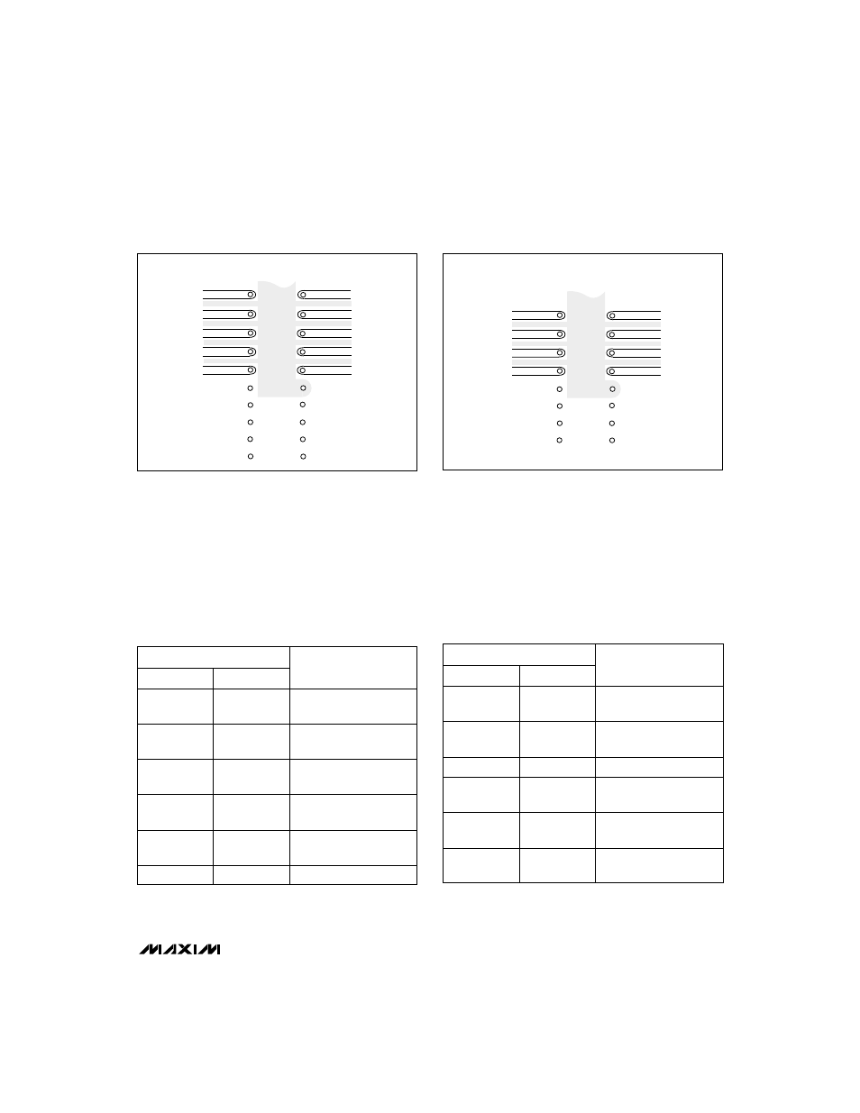
Figure 9. Suggested MAX509 PC Board Layout for Minimizing
Crosstalk (Bottom View)
OUTC
OUTD
V
DD
REFC
REFD
OUTB
OUTA
V
SS
REFB
REFA
SYSTEM GND
AGND
Figure 10. Suggested MAX510 PC Board Layout for Minimizing
Crosstalk (Bottom View)
OUTC
OUTD
V
DD
REFCD
OUTB
OUTA
V
SS
REFAB
SYSTEM GND
AGND
DAC CONTENTS
MSB
LSB
ANALOG
OUTPUT
1 1 1 1
1 1 1 1
255
+V
REF
(
––––
)
256
1 0 0 0
0 0 0 1
129
+V
REF
(
––––
)
256
1 0 0 0
0 0 0 0
128 V
REF
+V
REF
(
––––
)
= + –
–––
256 2
0 1 1 1
1 1 1 1
127
+V
REF
(
––––
)
256
0 0 0 0
0 0 0 0
0V
0 0 0 0
0 0 0 1
1
+V
REF
(
––––
)
256
Table 2. Unipolar Code Table
1
Note:
1LSB = (V
REF
) (2-8) = +V
REF
(
––––
)
256
Table 3. Bipolar Code Table
1 0 0 0
DAC CONTENTS
0 0 0 1
MSB
LSB
ANALOG
OUTPUT
1 1 1 1
1 1 1 1
127
+V
REF
(
––––
)
128
1
+V
REF
(
––––
)
128
1 0 0 0
0 0 0 0
0V
0 1 1 1
1 1 1 1
1
-V
REF
(
––––
)
128
0 0 0 0
0 0 0 0
128
-V
REF
(
––––
)
= -V
REF
128
0 0 0 0
0 0 0 1
127
-V
REF
(
––––
)
128