Wire serial-port operation – Rainbow Electronics DS1859 User Manual
Page 26
DS1859
Dual, Temperature-Controlled Resistors with
Internally Calibrated Monitors
26
____________________________________________________________________
operation, incremented by one. This data is maintained
as long as V
CC
is valid. If the most recent address was
the last byte in memory, then the register resets to the
first address.
Once the device address is clocked in and acknowl-
edged by the DS1859 with the R/W bit set to high, the
current address data word is clocked out. The master
does not respond with a zero, but does generate a
STOP condition afterwards.
Single Read
A random read requires a dummy byte write sequence to
load in the data byte address. Once the device and data
address bytes are clocked in by the master and acknowl-
edged by the DS1859, the master must generate another
START condition. The master now initiates a current
address read by sending the device address with the
R/W bit set high. The DS1859 acknowledges the device
address and serially clocks out the data byte.
Sequential Address Read
Sequential reads are initiated by either a current
address read or a random address read. After the mas-
ter receives the first data byte, the master responds
with an acknowledge. As long as the DS1859 receives
this acknowledge after a byte is read, the master can
clock out additional data words from the DS1859. After
reaching address FFh, it resets to address 00h.
The sequential read operation is terminated when the
master initiates a STOP condition. The master does not
respond with a zero.
The following section provides a detailed description of
the 2-wire theory of operation.
2-Wire Serial-Port Operation
The 2-wire serial-port interface supports a bidirectional
data transmission protocol with device addressing. A
device that sends data on the bus is defined as a trans-
mitter, and a device that receives data as a receiver.
The device that controls the message is called a mas-
ter. The devices that are controlled by the master are
slaves. The bus must be controlled by a master device
that generates the serial clock (SCL), controls the bus
access, and generates the START and STOP condi-
tions. The DS1859 operates as a slave on the 2-wire
bus. Connections to the bus are made through the
open-drain I/O lines SDA and SCL. The following I/O
terminals control the 2-wire serial port: SDA, SCL.
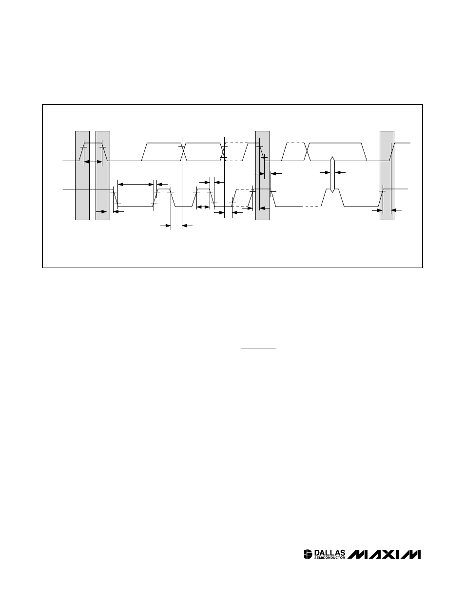
Timing diagrams for the 2-wire serial port can be found
in Figures 5 and 6. Timing information for the 2-wire
serial port is provided in the AC Electrical
Characteristics
table
for 2-wire serial communications.
The following bus protocol has been defined:
◆
Data transfer may be initiated only when the bus is
not busy.
◆
During data transfer, the data line must remain
stable whenever the clock line is high. Changes in
SDA
SCL
t
HD:STA
t
LOW
t
HIGH
t
R
t
F
t
BUF
t
HD:DAT
t
SU:DAT
REPEATED
START
t
SU:STA
t
HD:STA
t
SU:STO
t
SP
STOP
START
Figure 6. 2-Wire AC Characteristics