Table 6. main device, Table 7. auxiliary device – Rainbow Electronics DS1859 User Manual
Page 12
DS1859
Dual, Temperature-Controlled Resistors with
Internally Calibrated Monitors
12
____________________________________________________________________
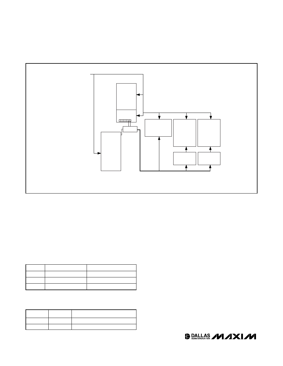
above is accessible only through the Main Device
address. This memory is organized as three tables. The
desired
table
can be selected by the contents of mem-
ory location 7Fh, Main Device. The Auxiliary Device
address has no access to the tables, but the Auxiliary
Device address can be mapped into the Main Device’s
memory space as a fourth
table
. Device addresses are
programmable with two control bits in EEPROM.
ADEN configures memory access to respond to differ-
ent device addresses (see
Tables
4 and 5).
The default device address for EEPROM-generated
addresses is A2h.
If the ADEN bit is 1, additional 128 bytes of EEPROM
are accessible through the Main Device, selected as
Table
00 (see
Figure
3). In this configuration, the
Auxiliary Device is not accessible. APEN controls the
protection of Table 00 regardless of ADEN’s setting.
ADFIX (address fixed) determines whether the Main
Device address is determined by an EEPROM byte
(
Table
01, byte 8Ch, when ADFIX = 1). There can be
up to 128 devices sharing a common 2-wire bus, with
each device having its own unique device address.
WPEN
MPEN
PROTECT MAIN
0
X
No
X
0
No
1
1
Yes
Table 6. Main Device
APEN
WPEN
PROTECT AUXILIARY
0
X
No
1
X
Yes
Table 7. Auxiliary Device
MAIN
DEVICE
MON LOOK-UP
TABLE CONTROL
R0 LOOK-UP
TABLE
AUXILIARY
DEVICE
80h
DEC
0
95
96
127
128
143
199
255
EN
EN
EN
5Fh
60h
EN
SEL
EN
SEL
FFh
7Fh
80h
80h
C7h
F0h
FFh
RESERVED
8Fh
TABLE SELECT
TABLE 00
MAIN DEVICE ENABLE
DECODER
0
F0h
FFh
RESERVED
R1 LOOK-UP
TABLE
EN
SEL
80h
C7h
TABLE 03
TABLE 02
TABLE 01
MEMORY PARTITION WITH ADEN BIT = 1
Figure 3. Memory Organization, ADEN = 1