Table 01h – Rainbow Electronics DS1859 User Manual
Page 19
DS1859
Dual, Temperature-Controlled Resistors with
Internally Calibrated Monitors
____________________________________________________________________
19
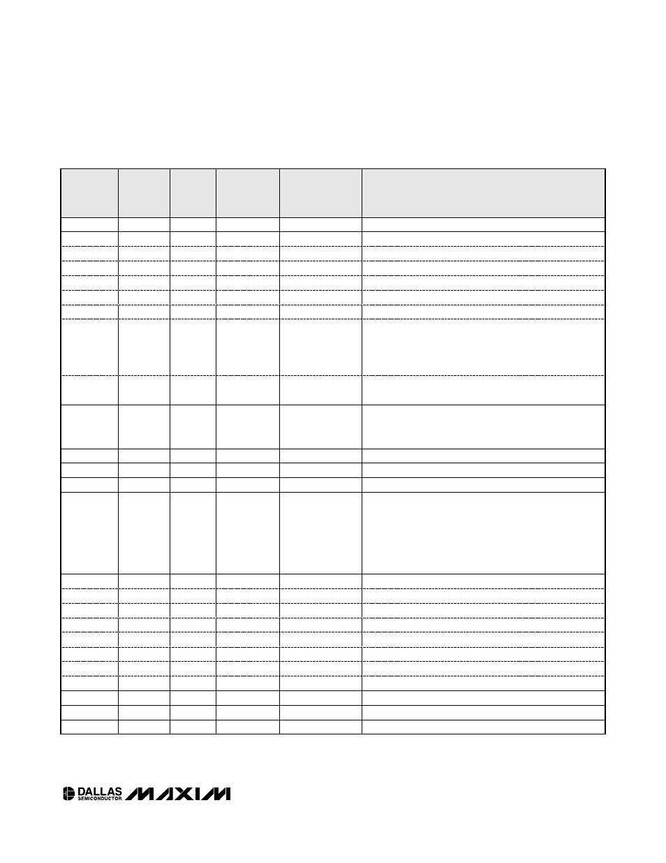
MEMORY
LOCATION
(hex)
EEPROM/
SRAM
R/W
DEFAULT
SETTING
(hex)
NAME OF
LOCATION
FUNCTION
80
SRAM
R/W
Mode
—
Bit 7
—
—
0
X
—
6
—
—
0
X
—
5
—
—
0
X
—
4
—
—
0
X
—
3
—
—
0
X
—
2
—
—
0
X
—
1
—
—
1
TEN
If TEN = 0, the resistors can be controlled manually. The
user sets the resistor in manual mode by writing to
addresses 82h and 83h in Table 01 to control resistors 0
and 1, respectively.
0
—
—
1
AEN
AEN = 0 is a test mode setting and provides manual
control of the temperature index (Table 01, address 81h).
81
SRAM
R
—
Temperature
index
This byte is the temperature-calculated index used to
select the address of resistor settings in the look-up
tables (Tables 02 and 03, addresses 80h through C7h).
82
SRAM
R/W
FF
Resistor 0
Resistor 0 position values from 00h to FFh.
83
SRAM
R/W
FF
Resistor 1
Resistor 1 position values from 00h to FFh.
84 to 87
SRAM
—
—
Reserved
—
88
EEPROM
R/W
Interrupt enable
This byte configures a maskable interrupt, determining
which event asserts a buffer 1 output (MINT set to 1, see
register 89h in Table 01). If any combination of
temperature, V
CC
, MON1, MON2, or MON3 is desired to
generate an interrupt, the corresponding bits are set to 1.
If interrupt generation is not desired, set all bits to 0.
Bit 7
—
—
1
TMP
—
6
—
—
1
V
CC
—
5
—
—
1
MON1
—
4
—
—
1
MON2
—
3
—
—
1
MON3
—
2
—
—
0
X
—
1
—
—
0
X
—
0
—
—
0
X
—
89
EEPROM
R/W
Configuration
—
Bit 7
—
—
0
X
—
6
—
—
0
X
Table 01h