Rainbow Electronics DS1868 User Manual
Ds1868 dual digital potentiometer chip, Features, Pin assignment pin description
1 of 14
100899
FEATURES
Ultra-lowpower consumption, quiet, pumpless
design
Two digitally controlled, 256-position
potentiometers
Serial port provides means for setting and
reading both potentiometers
Resistors can be connected in series to
provide increased total resistance
20-pin TSSOP, 16-pin SOIC, and 14-pin DIP
packages are available.
Resistive elements are temperature
compensated to
±0.3 LSB relative linearity
Standard resistance values:
-
DS1868-10
∼10 kΩ
-
DS1868-50
∼50 kΩ
-
DS1868-100
∼100 kΩ
+5V or ±3V operation
Operating Temperature Range:
-
Industrial: -40°C to 85°C
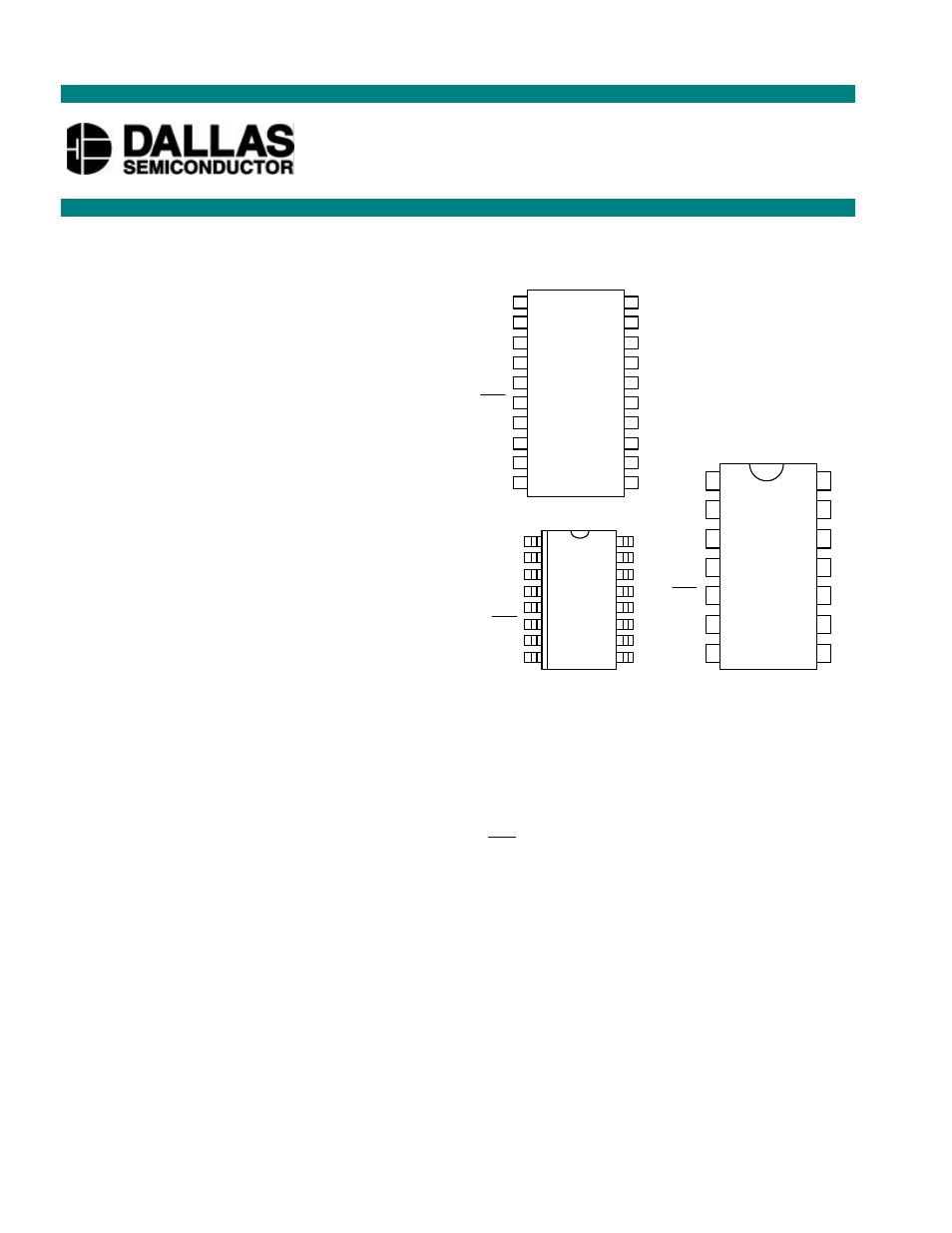
PIN ASSIGNMENT
PIN DESCRIPTION
L0, L1
- Low End of Resistor
H0, H1
- High End of Resistor
W0, W1
- Wiper Terminal of Resistor
S
OUT
- Stacked Configuration Output
RST
- Serial Port Reset Input
DQ
- Serial Port Data Input
CLK
- Serial Port Clock Input
C
OUT
- Cascade Port Output
V
CC
- +5 Volt Supply
GND
- Ground Connections
NC
- No Internal Connection
V
B
- Substrate Bias Voltage
DNC
- Do Not Connect
*All GND pins must be connected to ground.
DESCRIPTION
The DS1868 Dual Digital Potentiometer Chip consists of two digitally controlled solid-state
potentiometers. Each potentiometer is composed of 256 resistive sections. Between each resistive section
and both ends of the potentiometer are tap points which are accessible to the wiper. The position of the
DS1868
Dual Digital Potentiometer Chip
www.dalsemi.com
20-Pin TSSOP (173-mil)
V
B
DNC
H1
L1
W1
RST
CLK
DNC
DNC
GND
V
CC
DNC
DNC
S
OUT
W0
H0
L0
C
OUT
DNC
DQ
20
19
18
17
16
15
14
13
12
11
1
2
3
4
5
6
7
8
9
10
DS1868S 16-Pin SOIC (300-mil)
V
B
NC
H1
L1
W1
RST
CLK
GND
V
CC
NC
S
OUT
W0
H0
L0
C
OUT
DQ
16
15
14
13
12
11
10
9
1
2
3
4
5
6
7
8
14-Pin DIP (300-mil)
V
B
H1
L1
W1
RST
CLK
V
CC
S
OUT
W0
H0
L0
C
OUT
14
13
12
11
10
8
1
2
3
4
5
7
DQ
GND
9
6