Ac programming characteristics – Rainbow Electronics AT27BV512 User Manual
Page 8
AT27BV512
8
Notes:
1. V
CC
must be applied simultaneously or before OE/V
PP
and removed simultaneously or after OE/V
PP
.
2. This parameter is only sampled and is not 100% tested. Output Float is defined as the point where data is no longer driven—
see timing diagram.
3. Program Pulse width tolerance is 100
µ
sec
±
5%.
Note:
1. The AT27BV512 has the same Product Identification Code as the AT27C512R. Both are programming compatible.
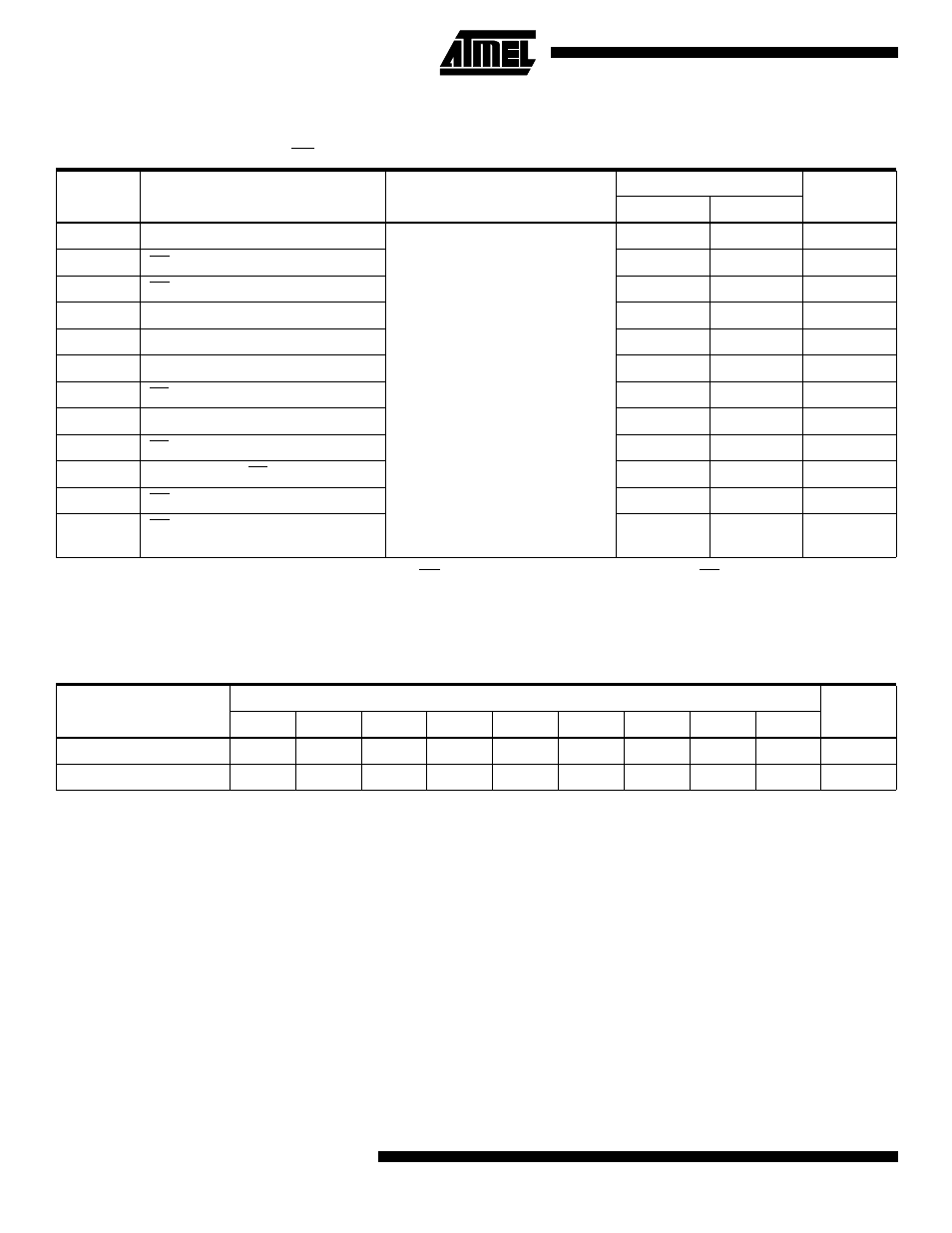
AC Programming Characteristics
T
A
= 25
±
5°C, V
CC
= 6.5
±
0.25V, OE/V
PP
= 13.0
±
0.25V
Symbol
Parameter
Test Conditions
(1)
Limits
Units
Min
Max
t
AS
Address Setup Time
Input Rise and Fall Times:
(10% to 90) 20 ns
Input Pulse Levels:
0.45V to 2.4V
Input Timing Reference Level:
0.8V to 2.0V
Output Timing Reference Level:
0.8V to 2.0V
2
µ
s
t
OES
OE/V
PP
Setup Time
2
µ
s
t
OEH
OE/V
PP
Hold Time
2
µ
s
t
DS
Data Setup Time
2
µ
s
t
AH
Address Hold Time
0
µ
s
t
DH
Data Hold Time
2
µ
s
t
DFP
CE High to Output Float Delay
(2)
0
130
ns
t
VCS
V
CC
Setup Time
2
µ
s
t
PW
CE Program Pulse Width
(3)
95
105
µ
s
t
DV
Data Valid from CE
(2)
1
µ
s
t
VR
OE/V
PP
Recovery Time
2
µ
s
t
PRT
OE/V
PP
Pulse Rise Time During
Programming
50
ns
Atmel’s 27BV512 Integrated Product Identification Code
(1)
Codes
Pins
Hex
Data
A0
O7
O6
O5
O4
O3
O2
O1
O0
Manufacturer
0
0
0
0
1
1
1
1
0
1E
Device Type
1
0
0
0
0
1
1
0
1
0D