General-purpose register file, Attiny11/12, Bit data bus – Rainbow Electronics ATtiny12 User Manual
Page 9
9
ATtiny11/12
1006C–09/01
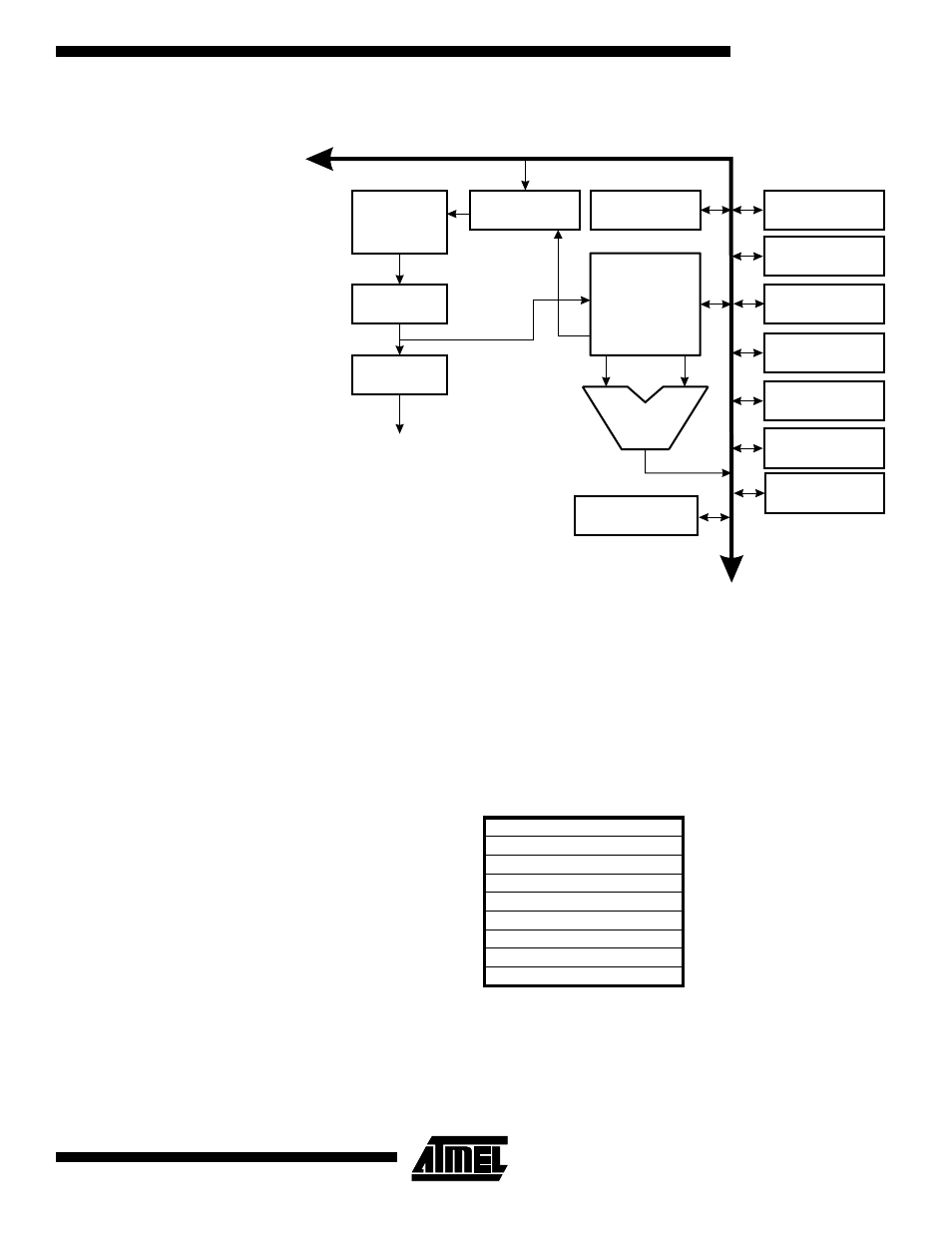
Figure 6. The ATtiny11/12 AVR RISC Architecture
A flexible interrupt module has its control registers in the I/O space with an additional
global interrupt enable bit in the status register. All the different interrupts have a sepa-
r a t e i n t e r r u p t v e c t o r i n t h e i n t e r r u p t v e c t o r t a b l e a t t h e b e g i n n i n g o f t h e
program memory. The different interrupts have priority in accordance with their interrupt
vector position. The lower the interrupt vector address, the higher the priority.
General-purpose
Register File
Figure 7 shows the structure of the 32 general-purpose registers in the CPU.
Figure 7. AVR
CPU General-purpose Working Registers
All the register operating instructions in the instruction set have direct- and single-cycle
access to all registers. The only exception is the five constant arithmetic and logic
instructions SBCI, SUBI, CPI, ANDI, and ORI between a constant and a register and the
LDI instruction for load-immediate constant data. These instructions apply to the second
half of the registers in the register file – R16..R31. The general SBC, SUB, CP, AND,
512 x 16
Program
Flash
Instruction
Register
Instruction
Decoder
Program
Counter
Control Lines
32 x 8
General-
purpose
Registers
ALU
Direct Addressing
Status
and Test
Control
Registers
Interrupt
Unit
8-bit
Timer/Counter
Watchdog
Timer
Analog
Comparator
6
I/O Lines
8-bit Data Bus
SPI Unit
(ATtiny12 only)
64 x 8 EEPROM
(ATtiny12 only)
7
0
R0
R1
R2
General-
…
purpose
…
Working
R28
Registers
R29
R30 (Z-register low byte)
R31 (Z-register high byte)