Reset sources, Attiny11/12 – Rainbow Electronics ATtiny12 User Manual
Page 17
17
ATtiny11/12
1006C–09/01
Reset Sources
The ATtiny11/12 provides three or four sources of reset:
•
Power-on Reset. The MCU is reset when the supply voltage is below the power-on
reset threshold (V
POT
).
•
External Reset. The MCU is reset when a low level is present on the RESET pin for
more than 50 ns.
•
Watchdog Reset. The MCU is reset when the Watchdog timer period expires and
the Watchdog is enabled.
•
Brown-out Reset. The MCU is reset when the supply voltage V
CC
falls below a
certain voltage (ATtiny12 only).
During reset, all I/O registers are then set to their initial values, and the program starts
execution from address $000. The instruction placed in address $000 must be an RJMP
– relative jump – instruction to the reset handling routine. If the program never enables
an interrupt source, the interrupt vectors are not used, and regular program code can be
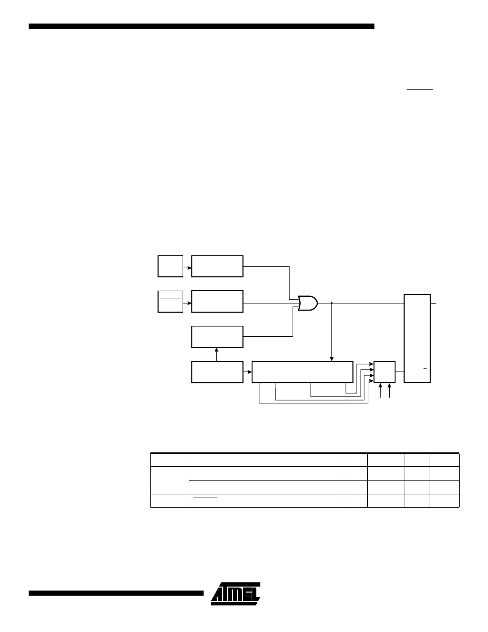
placed at these locations. The circuit diagram in Figure 16 shows the reset logic for the
ATtiny11. Figure 17 shows the reset logic for the ATtiny12. Table 6 defines the electrical
parameters of the reset circuitry for ATtiny11. Table 8 shows the parameters of the reset
circuitry for ATtiny12.
Figure 16. Reset Logic for the ATtiny11
Note:
1. The Power-on Reset will not work unless the supply voltage has been below V
POT
(falling).
Table 6. Reset Characteristics for the ATtiny11
Symbol
Parameter
Min
Typ
Max
Units
V
POT
Power-on Reset Threshold Voltage (rising)
1.0
1.4
1.8
V
Power-on Reset Threshold Voltage (falling)
0.4
0.6
0.8
V
V
RST
RESET Pin Threshold Voltage
0.6 V
CC
V
Power-on Reset
Circuit
Reset Circuit
Watchdog
Timer
On-chip
RC Oscillator
20-stage Ripple Counter
Q3
Q19
Q13
Q9
Q
Q
S
R
INTERNAL
RESET
POR
VCC
RESET
COUNTER RESET
FSTRT
CKSEL