Brown-out detection (attiny12), Attiny11/12 – Rainbow Electronics ATtiny12 User Manual
Page 22
22
ATtiny11/12
1006C–09/01
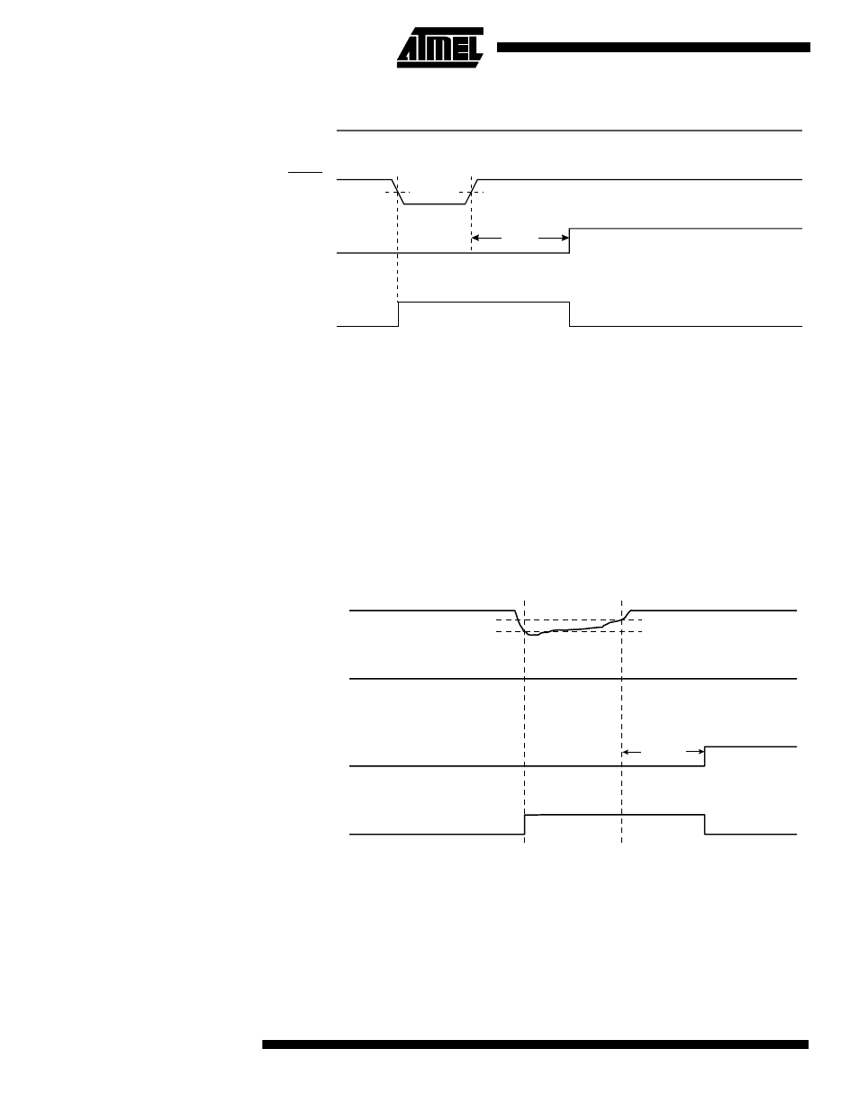
Figure 20. External Reset during Operation
Brown-out Detection
(ATtiny12)
ATtiny12 has an on-chip brown-out detection (BOD) circuit for monitoring the V
CC
level
during the operation. The BOD circuit can be enabled/disabled by the fuse BODEN.
When BODEN is enabled (BODEN programmed), and V
CC
decreases below the trigger
level, the brown-out reset is immediately activated. When V
CC
increases above the trig-
ger level, the brown-out reset is deactivated after a delay. The delay is defined by the
user in the same way as the delay of POR signal, in Table 5. The trigger level for the
BOD can be selected by the fuse BODLEVEL to be 1.8V (BODLEVEL unprogrammed),
or 2.7V (BODLEVEL programmed). The trigger level has a hysteresis of 50 mV to
ensure spike-free brown-out detection.
The BOD circuit will only detect a drop in V
CC
if the voltage stays below the trigger level
for longer than 7 µs for trigger level 2.7V, 24 µs for trigger level 1.8V (typical values).
Figure 21. Brown-out Reset during Operation (ATtiny12)
Note:
The hysteresis on V
BOT
: V
BOT +
= V
BOT
+ 25 mV, V
BOT-
= V
BOT
- 25 mV.
V
CC
TIME-OUT
INTERNAL
RESET
RESET
t
TOUT
V
RST
V
CC
RESET
TIME-OUT
INTERNAL
RESET
V
BOT-
V
BOT+
t
TOUT