Power-on reset for the attiny12, External reset, See figure 18 – Rainbow Electronics ATtiny12 User Manual
Page 21: Figure 19, Attiny11/12
21
ATtiny11/12
1006C–09/01
Power-on Reset for the
ATtiny12
A Power-on Reset (POR) pulse is generated by an on-chip detection circuit. The detec-
tion level is nominally 1.4V. The POR is activated whenever V
CC
is below the detection
level. The POR circuit can be used to trigger the start-up reset, as well as detect a fail-
ure in supply voltage.
The Power-on Reset (POR) circuit ensures that the device is reset from power-on.
Reaching the Power-on Reset threshold voltage invokes a delay counter, which deter-
mines the delay for which the device is kept in Reset after V
CC
rise. The time-out period
of the delay counter can be defined by the user through the CKSEL fuses. The different
selections for the delay period are presented in Table 9. The Reset signal is activated
again, without any delay, when the V
CC
decreases below detection level.
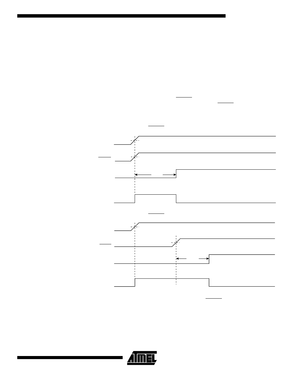
If the built-in start-up delay is sufficient, RESET can be connected to V
CC
directly or via
an external pull-up resistor. See Figure 18. By holding the RESET pin low for a period
after V
CC
has been applied, the Power-on Reset period can be extended. Refer to Fig-
ure 19 for a timing example on this.
Figure 18. MCU Start-up, RESET Tied to V
CC
.
Figure 19. MCU Start-up, RESET Extended Externally
External Reset
An external reset is generated by a low level on the RESET pin. Reset pulses longer
than 50 ns will generate a reset, even if the clock is not running. Shorter pulses are not
guaranteed to generate a reset. When the applied signal reaches the Reset Threshold
Voltage – V
RST
– on its positive edge, the delay timer starts the MCU after the Time-out
period (t
TOUT
) has expired.
V
CC
RESET
TIME-OUT
INTERNAL
RESET
t
TOUT
V
POT
V
RST
V
CC
TIME-OUT
INTERNAL
RESET
RESET
t
TOUT
V
POT
V
RST