Attiny11/12 – Rainbow Electronics ATtiny12 User Manual
Page 16
16
ATtiny11/12
1006C–09/01
The most typical and general program setup for the reset and interrupt vector addresses
for the ATtiny11 are:
Address
Labels
Code
Comments
$000
rjmp
RESET
; Reset handler
$001
rjmp
EXT_INT0
; IRQ0 handler
$002
rjmp
PIN_CHANGE
; Pin change handler
$003
rjmp
TIM0_OVF
; Timer0 overflow handler
$004
rjmp
ANA_COMP
; Analog Comparator handler
;
$005
MAIN:
xxx
; Main program start
…
…
…
…
The most typical and general program setup for the reset and interrupt vector addresses
for the ATtiny12 are:
Address
Labels
Code
Comments
$000
rjmp
RESET
; Reset handler
$001
rjmp
EXT_INT0
; IRQ0 handler
$002
rjmp
PIN_CHANGE
; Pin change handler
$003
rjmp
TIM0_OVF
; Timer0 overflow handler
$004
rjmp
EE_RDY
; EEPROM Ready handler
$005
rjmp
ANA_COMP
; Analog Comparator handler
;
$006
MAIN:
xxx
; Main program start
…
…
…
…
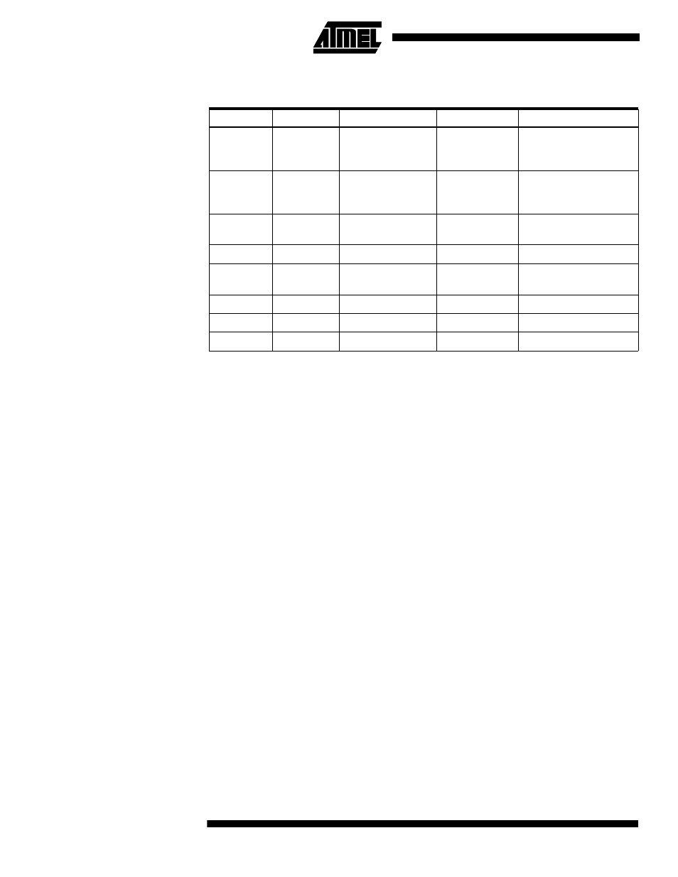
Table 5. Reset and Interrupt Vectors
Vector No.
Device
Program Address
Source
Interrupt Definition
1
ATtiny11
$000
RESET
External Pin, Power-on
Reset and Watchdog
Reset
1
ATtiny12
$000
RESET
External Pin, Power-on
Reset, Brown-out Reset
and Watchdog Reset
2
ATtiny11/12
$001
INT0
External Interrupt
Request 0
3
ATtiny11/12
$002
I/O Pins
Pin Change Interrupt
4
ATtiny11/12
$003
TIMER0, OVF0
Timer/Counter0
Overflow
5
ATtiny11
$004
ANA_COMP
Analog Comparator
5
ATtiny12
$004
EE_RDY
EEPROM Ready
6
ATtiny12
$005
ANA_COMP
Analog Comparator