Figure 2. rising edge pullup – Rainbow Electronics DS2482-800 User Manual
Page 6
DS2482-800: Eight-Channel 1-Wire Master
6 of 22
Channel Selection Register
The content of the Channel Selection Register specifies which of the channels is selected and will be the target of
subsequent 1-Wire communication commands. The DS2482-800 supports eight 1-Wire communication channels
IO0 to IO7. Only one of these channels can be active/selected at any time. Once selected, a 1-Wire channel
remains selected until a different channel is selected through the Channel Select command or by initiating a
device reset. After a device reset (power-up cycle or initiated by the Device Reset command) the IO0 channel is
selected.
Configuration Register
The DS2482 supports allows four 1-Wire features that are enabled or selected through the Configuration Register.
These features are:
§ Active Pullup (APU)
§ Presence Pulse Masking (PPM)
§ Strong Pullup (SPU)
§ 1-Wire Speed (1WS)
These features can be selected in any combination. They apply equally to all 1-Wire channels. While APU, PPM
and 1WS maintain their state, SPU returns to its inactive state as soon as the strong pullup has ended.
Configuration Register Bit Assignment
bit 7
bit 6
bit 5
bit 4
bit 3
bit 2
bit 1
bit 0
1WS SPU PPM APU 1WS SPU PPM APU
After a device reset (power-up cycle or initiated by the Device Reset command) the Configuration Register reads
00h. When writing to the Configuration Register, the new data is accepted only if the upper nibble (bits 7 to 4) is the
one's complement of the lower nibble (bits 3 to 0). When read, the upper nibble is always 0h.
Active Pullup (APU)
The APU bit controls whether an active pullup (controlled slew-rate transistor) or a passive pullup (R
WPU
resistor)
will be used to drive a 1-Wire line from low to high. When APU = 0, active pullup is disabled (resistor mode). Active
Pullup should be selected if the 1-Wire line has a substantial length (30 meters or more) or if there is a large
number (~20 or more) of devices connected to a 1-Wire line. The active pullup does not apply to the rising
edge of a presence pulse or a recovery after a short on the 1-Wire line.
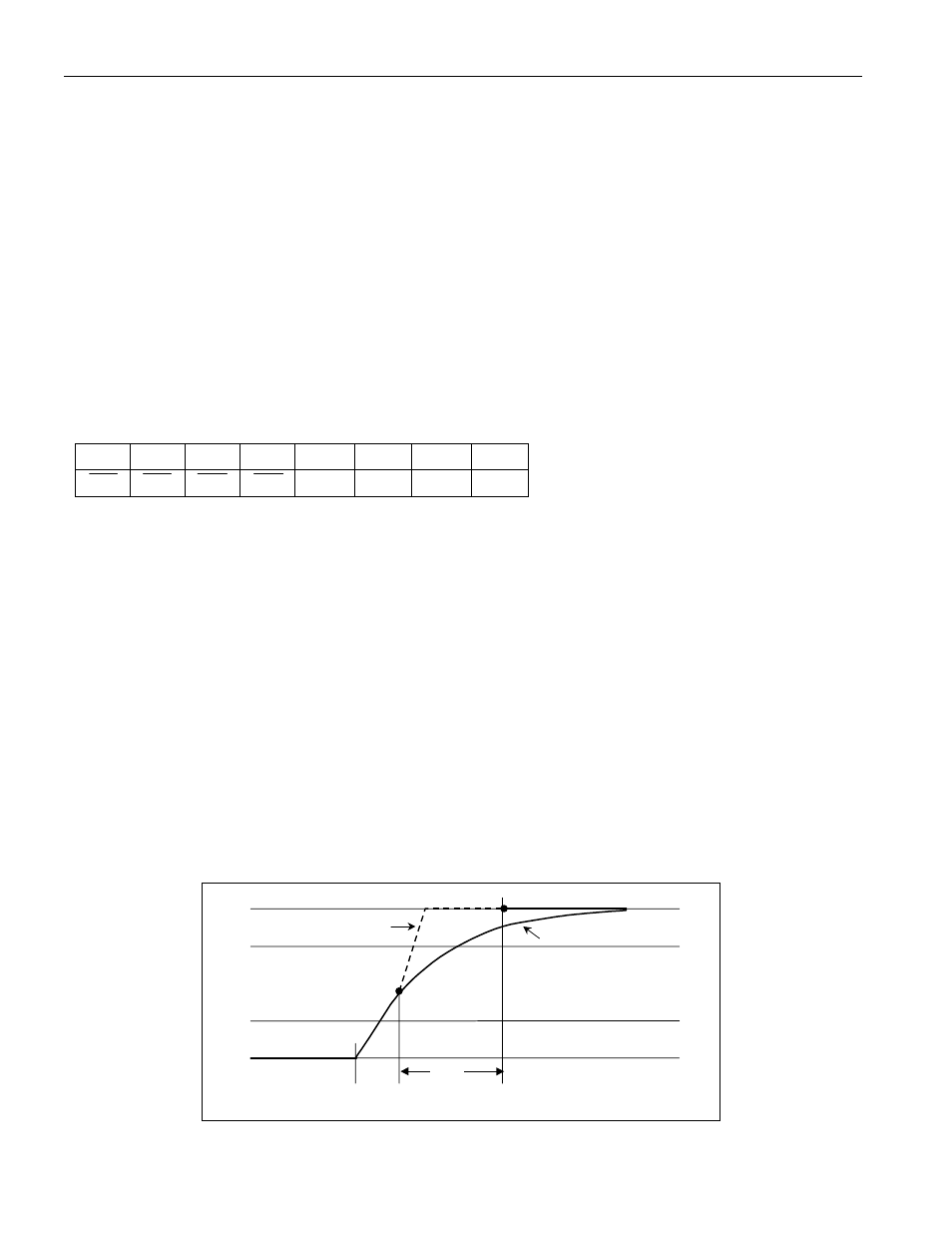
The circuit that controls rising edges (Figure 2) operates as follows: At t1 the pulldown (from DS2482 or 1-Wire
slave) ends. From this point on the 1-Wire bus is pulled high through R
WPU
internal to the DS2482. V
CC
and the
capacitive load of the 1-Wire line determine the slope. In case that active pullup is disabled (APU = 0), the resistive
pullup continues, as represented by the solid line. With active pullup enabled (APU = 1), when at t2 the voltage has
reached a level between V
IL1max
and V
IH1min
, the DS2482 actively pulls the 1-Wire line high applying a controlled
slew rate, as represented by the dashed line. The active pullup continues until t
APUOT
is expired at t3. From that time
on the resistive pullup will continue.
Figure 2. Rising Edge Pullup
V
CC
0V
1-Wire bus is
discharged
V
IL1MAX
V
IH1MIN
t
APUOT
t
1
t
2
t
3
APU = 1
APU = 0