Detailed description – Rainbow Electronics DS2482-800 User Manual
Page 5
DS2482-800: Eight-Channel 1-Wire Master
5 of 22
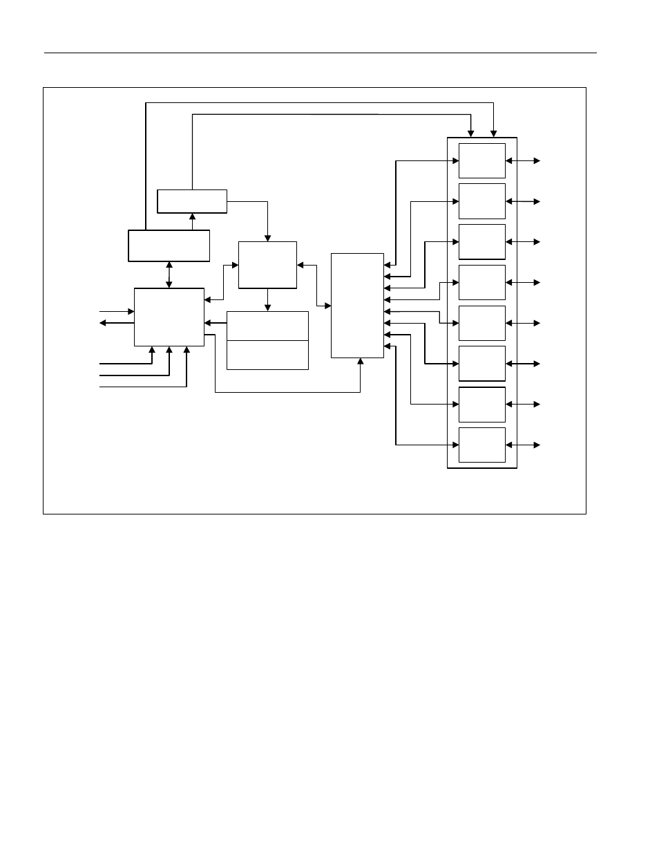
Figure 1. Block Diagram
I²C
Interface
Controller
SDA
SCL
Config
Register
I/O
Controller
Status
Register
Line
XCVR
Channel
Select
Line
XCVR
Line
XCVR
Line
XCVR
Line
XCVR
Line
XCVR
Line
XCVR
Line
XCVR
AD0
AD1
AD2
IO0
IO1
IO2
IO3
IO4
IO5
IO6
IO7
Read Data
Register
T-Time OSC
DETAILED DESCRIPTION
The DS2482-800 is a self-timed 8-channel 1-Wire master, which supports advanced 1-Wire waveform features
including standard and Overdrive speeds, active pullup, strong pullup for power delivery, and presence pulse
masking. Once supplied with command and data, the I/O controller of the DS2482 performs time-critical 1-Wire
communication functions such as reset/presence detect cycle, read-byte, write-byte, single-bit R/W and triplet for
ROM Search, without requiring interaction with the host processor. The host obtains feedback (completion of a 1-
Wire function, presence pulse, 1-Wire short, search direction taken) through the Status Register and data through
the Read Data register. The DS2482 communicates with a host processor through its I²C bus interface in standard-
mode or in fast-mode. The logic state of three address pins (2 address pins with the 1-channel version) determines
the I²C slave address of the DS2482, allowing up to 8 devices operating on the same bus segment without
requiring a hub.
DEVICE REGISTERS
The DS2482 has four registers that the I²C host can read: Channel Selection, Configuration, Status, and Read
Data. These registers are addressed by a read pointer. The position of the read pointer, i.e., the register that the
host will read in a subsequent read access, is defined by the instruction that the has DS2482 executed last. The
host has read and write access to the Channel Selection and Configuration Registers to select one of several 1-
Wire channels and to enable certain 1-Wire features.