Figure 11. application schematic, Application information – Rainbow Electronics DS2482-800 User Manual
Page 21
DS2482-800: Eight-Channel 1-Wire Master
21 of 22
Case C: 1-Wire busy (1WB = 1)
S
AD,0
A
1WT
A\
P
The master should stop and restart as soon as the DS2482 does not acknowledge the command code.
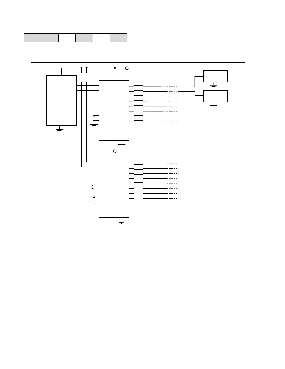
Figure 11. Application Schematic
(I²C port)
µC
DS2482-800
DS2482-800
1-Wire
Device #1
1-Wire
Device #2
1-Wire lines
*R
t
* R
t
Line termination resistor, typically 100
W
R
P
I²C pull-up resistor, see Application Information
for R
P
sizing.
*R
t
*R
P
IO0
IO1
IO2
IO3
IO4
IO5
IO6
IO7
AD0
AD1
AD2
SDA
SCL
V
CC
SDA
SCL
AD0
AD1
AD2
IO0
IO1
IO2
IO3
IO4
IO5
IO6
IO7
V
CC
V
CC
Application Information
SDA and SCL Pullup Resistors
SDA is an open-drain output on the DS2482 that requires a pullup resistor to realize high logic levels. Because the
DS2482 uses SCL only as input (no clock stretching) the master can drive SCL either through an open-
drain/collector output with a pullup resistor or a push-pull output.
Pullup Resistor R
P
Sizing
According to the I²C specification, a slave device must be able to sink at least 3mA at a V
OL
of 0.4V. This DC
condition determines the minimum value of the pullup resistor: Rpmin = (V
CC
- 0.4V)/3mA. With an operating
voltage of 5.5V, the minimum value for the pullup resistor is 1.7k
W. The "Minimum RP" line in Figure 12 shows how
the minimum pullup resistor changes with the operating voltage.
For I²C systems, the rise time and fall time are measured from 30% to 70% of the pullup voltage. The maximum
bus capacitance C
B
is 400pF. The maximum rise time at standard speed must not exceed 1000ns and 300ns at
fast speed. Assuming maximum rise time, the maximum resistor value at any given capacitance C
b
is calculated
as: Rpmaxs = 1000ns/(C
B
*ln(7/3)) (standard speed) and Rpmaxf = 300ns/(C
B
*ln(7/3)) (fast speed). For a bus